ARTE
BELEZA E BEM-ESTAR
ARTESANATO
CULTURA E HISTÓRIA
ENTRETENIMENTO
MEIO AMBIENTE
COMIDA E BEBIDAS
ENGENHARIA REVERSA
CIÊNCIAS
ESPORTES
TECNOLOGIA
TECNOLOGIA VESTÍVEL
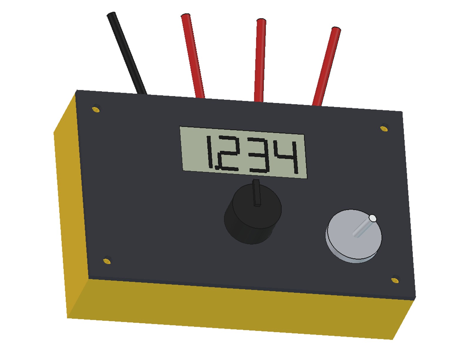


Multimeter: a Low-Voltage Pocket Meter on the ICL7106 Dual-Slope Converter (after Ammann, 1967)
A 3 1/2-digit digital multimeter for low-voltage projects: 2 V and 20 V DC, 200 mA and 2 kohm. One ICL7106 chip does the measuring by the dual-slope method Stephan Ammann patented in 1967: it integrates the input for a fixed time, then times how long a reference takes to bring it back to zero. Built on perfboard in a printed case. Never for mains.
Intermediário
About 1 day
Instruções
1
1
The dual-slope method
The dual-slope method
US 3,316,547 (Ammann, Fairchild, 1967): integrate the input over a fixed time, then integrate a reference of opposite sign until the integrator is back where it started. The time that takes, counted in clock pulses, is the ratio of input to reference, so the clock and the capacitor's exact values cancel out. The ICL7106 does this on one chip and drives the LCD directly.
2
2
Clock, ranges and the ohms circuit
Clock, ranges and the ohms circuit
A carregar o notebook Jupyter…
3
3
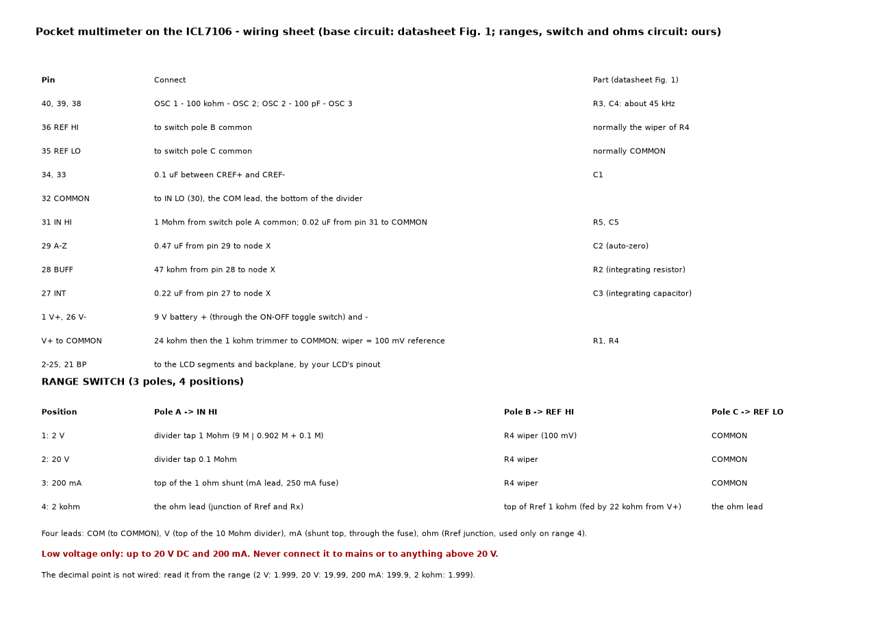
Print the wiring sheet
Print the wiring sheet
Pin by pin, the base circuit (datasheet Fig. 1 values) and the range switch table.
4
4
Print the case
Print the case
Floor down, no supports, PETG. Four holes in the top end for the leads.
Materiais para este passo:
 Filamento PETG60 g
Ferramentas necessárias:
 Impressora 3D de filamento (FDM)
5
5
Print the lid
Print the lid
Flat, no supports. Trim the LCD window to your display; the two round holes take the range switch and the toggle switch.
Materiais para este passo:
Filamento PETG30 gFerramentas necessárias:
Impressora 3D de filamento (FDM)6
6
Change the case (optional)
Change the case (optional)
The FreeCAD script that made the case: OUT=. freecadcmd build_all.py
build_all.pypython
Ferramentas necessárias:
 Paquímetro digital de 6 polegadas
7
7
Build the converter
Build the converter
On perfboard, wire the ICL7106 as the sheet's first table: oscillator 100 kohm and 100 pF; reference 24 kohm and the 1 kohm trimmer; 0.1 uF reference capacitor; 47 kohm, 0.47 uF and 0.22 uF (polypropylene) to node X; 1 Mohm and 0.02 uF at IN HI. Connect the LCD segments and backplane by your LCD's pinout.
Materiais para este passo:
 Circuito integrado1 piece (ICL7106, 40-pin DIP)
 Visor LCD de segmentos1 piece (3 1/2-digit, static drive)
 Placa perfurada / placa de prototipagem1 peça
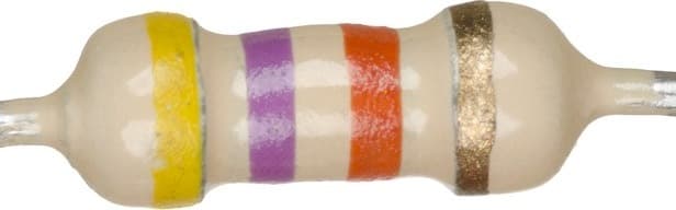
 Conjunto de resistências de precisão8 piece (1 %: 24k, 47k, 100k, 1M, 22k, 1k and the divider below)
 Kit de condensadores5 piece (0.1, 0.47, 0.22 polypropylene, 0.02 uF, 100 pF)
 Potenciómetro1 piece (1 kohm trimmer)
 Fio de solda5 g
Ferramentas necessárias:
 Ferro de soldar
8
8
Wire the ranges
Wire the ranges
Divider from the V lead to COMMON: 4.7 M + 4.3 M, then 820 k + 82 k, then 100 k (2 V tap between the 4.3 M and the 820 k; 20 V tap between the 82 k and the 100 k). Shunt: mA lead, 250 mA fuse, 1 ohm 1 % to COMMON. Ohms: V+, 22 kohm, 1 kohm Rref, ohm lead. Wire the 3-pole 4-position switch as the sheet's second table; power through the toggle switch.
Materiais para este passo:
Conjunto de resistências de precisão6 piece (1 %: 4.7M, 4.3M, 820k, 82k, 100k) Kit de resistências1 piece (1 ohm, 0.5 W)
 Comutador rotativo1 piece (3 pole, 4 position)
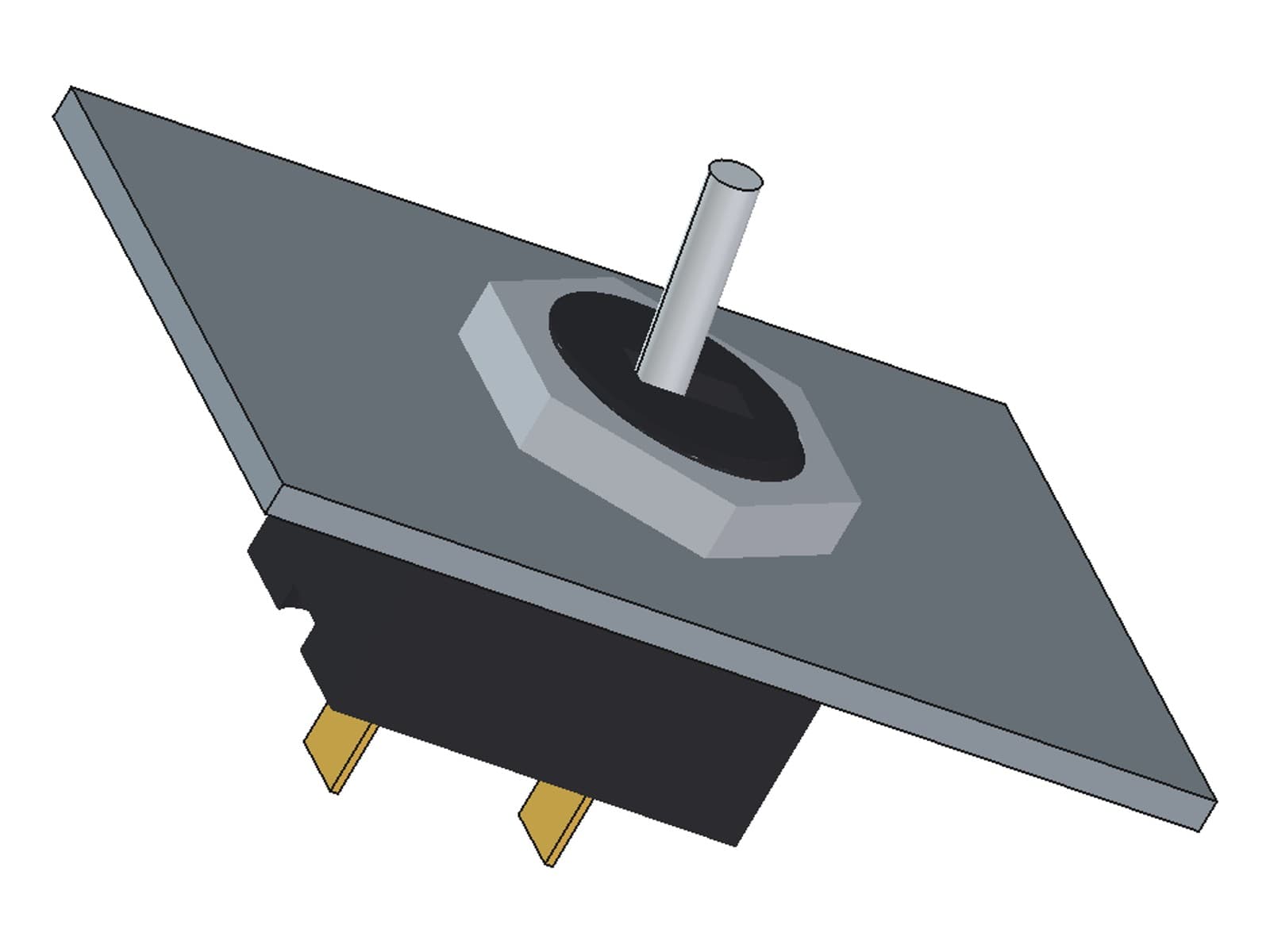
 Interruptor de alavanca1 peça
 Fusível1 piece (250 mA)
 Porta-fusíveis CC1 peça
 Bateria1 piece (9 V)
 Fio de ligação1 m
Ferramentas necessárias:
Ferro de soldar Descarnador de fios
9
9
Fit it in the case
Fit it in the case
Put the four leads (COM black; V, mA and ohm red) through their holes and knot them inside. Fix the board and battery with tape, the switches in the lid. Close with 4 x M3 x 10.
Materiais para este passo:
 Cabos de ensaio com pinças jacaré4 peças
 Fita de dupla face0.2 m
 Parafuso de cabeça cilíndrica com sextavado interior4 piece (M3 x 10)
Ferramentas necessárias:
 Jogo de chaves Allen
10
10
Calibrate
Calibrate
On the 2 V range, measure a steady voltage (a 1.5 V cell) with a good meter and with this one; turn the trimmer until they agree. Check the other ranges against the good meter.
Ferramentas necessárias:
 Multímetro digital de laboratório
11
11
Troubleshooting
Troubleshooting
Meter problems and fixes.
Flow
Loading...
12
12
History and honest limits
History and honest limits
Stephan K. Ammann, assignor to Fairchild: US 3,316,547, "Integrating Analog-to-Digital Converter", filed 15 July 1964, granted 25 April 1967. Chip values from the Intersil ICL7106 datasheet. Ours: the ranges, the divider, the shunt, the ohms circuit and the case. Low voltage only: up to 20 V DC and 200 mA; never on mains. Accuracy depends on your resistors (1 %) and calibration. Not built by us yet.
Materiais
18- 90 gReferência
- 1 piece (ICL7106, 40-pin DIP)Referência
- 1 piece (3 1/2-digit, static drive)Referência
- Referência
- 6 piece (1 %: 4.7M, 4.3M, 820k, 82k, 100k)Referência
- 5 piece (0.1, 0.47, 0.22 polypropylene, 0.02 uF, 100 pF)Referência
- Referência
- 5 gReferência
- Referência
- 1 piece (3 pole, 4 position)Referência
- Referência
- 1 piece (250 mA)Referência
- 1 peçaReferência
- 1 piece (9 V)Referência
- Referência
- Referência
- 0.2 mReferência
- 4 piece (M3 x 10)Referência
Ferramentas necessárias
6- Referência
- Referência
- 2 vendors sell this, none ship to you yetReferência
- Referência
- Referência
- Referência
Ficheiros de design
3Materiais de Blueprints conectados

Este projeto faz

CC0 Domínio Público
Este blueprint é liberado sob CC0. Você é livre para copiar, modificar, distribuir e usar este trabalho para qualquer finalidade, sem pedir permissão.
Apoie o Maker comprando produtos através do Blueprint, onde ele ganha uma Comissão Maker definida pelos vendedores, ou crie uma nova versão deste Blueprint e inclua-o como conexão no seu próprio Blueprint para compartilhar receita.