/*
  Pocket Morse decoder - firmware for ATmega328P-AU, internal 8 MHz, CR2032 (3 V)
  Board: Arduino Pro or Pro Mini, ATmega328P (3.3V, 8 MHz)  (fqbn arduino:avr:pro:cpu=8MHzatmega328)
  Fuses for the internal 8 MHz RC oscillator (set once with an ISP programmer):
    lfuse 0xE2, hfuse 0xD9, efuse 0xFF (brown-out detector off to save the coin cell)
  Upload with "Upload Using Programmer" over the 2x3 ISP header.

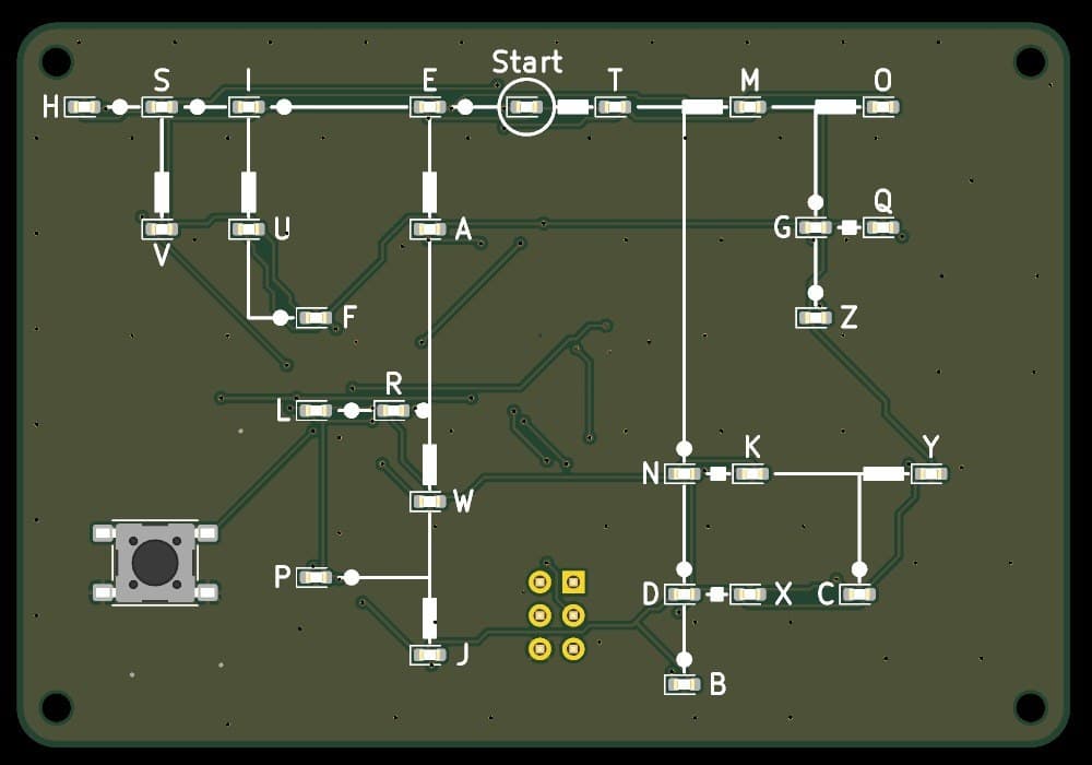
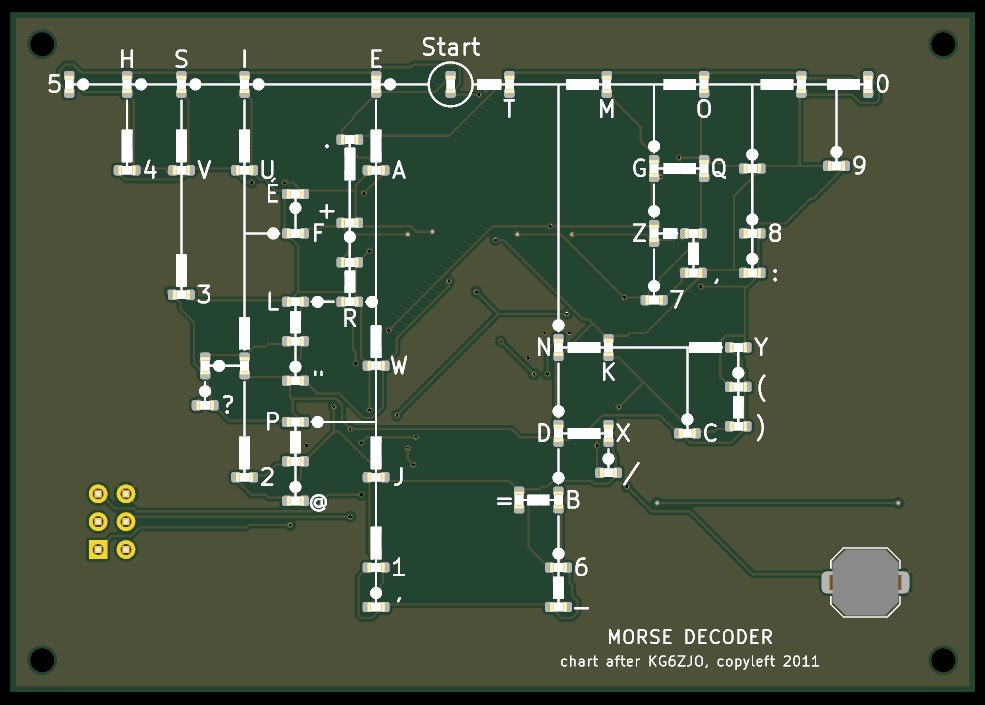
  59 LEDs are charlieplexed on 9 pins (each pin through its own 300 ohm resistor).
  Only one LED is ever lit.  Button on INT0 (D2) to GND, internal pull-up.
*/
#include <avr/sleep.h>
#include <avr/power.h>
#include <avr/pgmspace.h>

// ---------------- timings (milliseconds) ----------------
const unsigned long DASH_THRESHOLD_MS = 250;    // press shorter = dot, longer (or equal) = dash
const unsigned long CHAR_GAP_MS       = 700;    // no press for this long ends the character
const unsigned long IDLE_SLEEP_MS     = 30000;  // no press for this long -> all off, power-down sleep
const unsigned long BLINK_ON_MS       = 150;    // result blink: LED on time
const unsigned long BLINK_OFF_MS      = 150;    // result blink: LED off time
const uint8_t       BLINK_COUNT       = 3;      // number of result blinks
const unsigned long DEBOUNCE_MS       = 20;     // button debounce time

// ---------------- hardware ----------------
const uint8_t BUTTON_PIN = 2;                   // PD2 / INT0
// charlieplex lines L1..L9 -> PC0..PC5, PD0, PD1, PD3
const uint8_t LINE_PIN[9] = {A0, A1, A2, A3, A4, A5, 0, 1, 3};
const uint8_t MAX_CODE_LEN = 7;

struct Node { uint8_t len; uint8_t bits; uint8_t anode; uint8_t cathode; };
// bits: symbol j of the code is bit j (1 = dash). Index 0 is Start.
const Node NODES[] PROGMEM = {
  {0, 0x00, 0, 8},  // D1 S Start
  {1, 0x01, 3, 8},  // D2 - T
  {1, 0x00, 8, 0},  // D3 . E
  {2, 0x03, 3, 6},  // D4 -- M
  {2, 0x01, 6, 5},  // D5 -. N
  {2, 0x02, 0, 3},  // D6 .- A
  {2, 0x00, 8, 1},  // D7 .. I
  {3, 0x07, 3, 7},  // D8 --- O
  {3, 0x03, 6, 7},  // D9 --. G
  {3, 0x05, 5, 6},  // D10 -.- K
  {3, 0x01, 5, 2},  // D11 -.. D
  {3, 0x06, 4, 1},  // D12 .-- W
  {3, 0x02, 1, 7},  // D13 .-. R
  {3, 0x04, 1, 3},  // D14 ..- U
  {3, 0x00, 8, 3},  // D15 ... S
  {4, 0x0F, 3, 5},  // D16 ---- _
  {4, 0x07, 5, 7},  // D17 ---. _
  {4, 0x0B, 7, 6},  // D18 --.- Q
  {4, 0x03, 7, 8},  // D19 --.. Z
  {4, 0x0D, 8, 2},  // D20 -.-- Y
  {4, 0x05, 6, 2},  // D21 -.-. C
  {4, 0x09, 6, 0},  // D22 -..- X
  {4, 0x01, 2, 5},  // D23 -... B
  {4, 0x0E, 0, 1},  // D24 .--- J
  {4, 0x06, 2, 4},  // D25 .--. P
  {4, 0x0A, 1, 2},  // D26 .-.- _
  {4, 0x02, 7, 1},  // D27 .-.. L
  {4, 0x0C, 7, 2},  // D28 ..-- _
  {4, 0x04, 2, 1},  // D29 ..-. F
  {4, 0x08, 3, 4},  // D30 ...- V
  {4, 0x00, 8, 4},  // D31 .... H
  {5, 0x1F, 5, 3},  // D32 ----- 0
  {5, 0x0F, 7, 5},  // D33 ----. 9
  {5, 0x07, 8, 7},  // D34 ---.. 8
  {5, 0x13, 6, 8},  // D35 --..- _
  {5, 0x03, 8, 6},  // D36 --... 7
  {5, 0x0D, 2, 8},  // D37 -.--. (
  {5, 0x09, 0, 6},  // D38 -..-. /
  {5, 0x11, 0, 2},  // D39 -...- =
  {5, 0x01, 5, 0},  // D40 -.... 6
  {5, 0x1E, 1, 5},  // D41 .---- 1
  {5, 0x16, 0, 4},  // D42 .--.- _
  {5, 0x0A, 3, 2},  // D43 .-.-. +
  {5, 0x12, 2, 7},  // D44 .-..- _
  {5, 0x1C, 4, 0},  // D45 ..--- 2
  {5, 0x0C, 7, 4},  // D46 ..--. _
  {5, 0x04, 3, 1},  // D47 ..-.. É
  {5, 0x18, 1, 4},  // D48 ...-- 3
  {5, 0x10, 4, 3},  // D49 ....- 4
  {5, 0x00, 4, 8},  // D50 ..... 5
  {6, 0x07, 8, 5},  // D51 ---... :
  {6, 0x33, 5, 8},  // D52 --..-- ,
  {6, 0x2D, 2, 6},  // D53 -.--.- )
  {6, 0x21, 0, 5},  // D54 -....- -
  {6, 0x1E, 5, 1},  // D55 .----. '
  {6, 0x16, 2, 0},  // D56 .--.-. @
  {6, 0x2A, 3, 0},  // D57 .-.-.- .
  {6, 0x12, 4, 2},  // D58 .-..-. "
  {6, 0x0C, 4, 7},  // D59 ..--.. ?
};
const uint8_t NODE_COUNT = sizeof(NODES) / sizeof(NODES[0]);
const uint8_t START_NODE = 0;
const int8_t  NO_NODE = -1;

volatile bool wokeUp = false;

void allOff() {
  for (uint8_t i = 0; i < 9; i++) {
    pinMode(LINE_PIN[i], INPUT);
    digitalWrite(LINE_PIN[i], LOW);
  }
}

void lightNode(int8_t idx) {
  allOff();
  if (idx < 0 || idx >= NODE_COUNT) return;
  uint8_t a = pgm_read_byte(&NODES[idx].anode);
  uint8_t k = pgm_read_byte(&NODES[idx].cathode);
  digitalWrite(LINE_PIN[k], LOW);
  pinMode(LINE_PIN[k], OUTPUT);
  digitalWrite(LINE_PIN[a], HIGH);
  pinMode(LINE_PIN[a], OUTPUT);
}

int8_t findNode(uint8_t len, uint8_t bits) {
  for (uint8_t i = 0; i < NODE_COUNT; i++) {
    if (pgm_read_byte(&NODES[i].len) == len && pgm_read_byte(&NODES[i].bits) == bits) return i;
  }
  return NO_NODE;
}

bool buttonDown() { return digitalRead(BUTTON_PIN) == LOW; }

// wait until the button state is stable; returns that state
bool debouncedState() {
  bool s = buttonDown();
  unsigned long t = millis();
  while (millis() - t < DEBOUNCE_MS) {
    if (buttonDown() != s) { s = buttonDown(); t = millis(); }
  }
  return s;
}

void blink(int8_t idx) {
  for (uint8_t i = 0; i < BLINK_COUNT; i++) {
    lightNode(idx); delay(BLINK_ON_MS);
    allOff();       delay(BLINK_OFF_MS);
  }
}

void wakeISR() {
  detachInterrupt(digitalPinToInterrupt(BUTTON_PIN));
  wokeUp = true;
}

void goToSleep() {
  allOff();
  while (debouncedState()) {}              // make sure the button is released
  uint8_t adcsra = ADCSRA;
  ADCSRA = 0;                               // ADC off
  set_sleep_mode(SLEEP_MODE_PWR_DOWN);
  noInterrupts();
  wokeUp = false;
  EIFR = bit(INTF0);
  attachInterrupt(digitalPinToInterrupt(BUTTON_PIN), wakeISR, LOW);  // level interrupt wakes from power-down
  sleep_enable();
  sleep_bod_disable();
  interrupts();
  sleep_cpu();
  sleep_disable();
  ADCSRA = adcsra;
  while (debouncedState()) {}              // the waking press only wakes the board
}

uint8_t codeLen = 0;
uint8_t codeBits = 0;
bool    codeValid = true;
unsigned long lastActivity = 0;

void resetToStart() {
  codeLen = 0; codeBits = 0; codeValid = true;
  lightNode(START_NODE);
}

void setup() {
  for (uint8_t p = 4; p <= 13; p++) pinMode(p, INPUT_PULLUP);  // unused pins: no floating inputs
  pinMode(BUTTON_PIN, INPUT_PULLUP);
  allOff();
  power_spi_disable();
  power_twi_disable();
  power_usart0_disable();
  resetToStart();
  lastActivity = millis();
}

void loop() {
  unsigned long now = millis();

  if (debouncedState()) {                    // button pressed
    unsigned long pressStart = millis();
    while (debouncedState()) {}
    unsigned long pressLen = millis() - pressStart;
    bool dash = pressLen >= DASH_THRESHOLD_MS;
    if (codeValid && codeLen < MAX_CODE_LEN) {
      if (dash) codeBits |= (1 << codeLen);
      codeLen++;
      int8_t n = findNode(codeLen, codeBits);
      if (n == NO_NODE) { codeValid = false; allOff(); }
      else lightNode(n);
    } else {
      codeValid = false; allOff();
    }
    lastActivity = millis();
    return;
  }

  if (codeLen > 0 && now - lastActivity >= CHAR_GAP_MS) {   // end of character
    if (codeValid) blink(findNode(codeLen, codeBits));
    else blink(START_NODE);
    resetToStart();
    lastActivity = millis();   // idle time counts from the end of the character
    return;
  }

  if (codeLen == 0 && now - lastActivity >= IDLE_SLEEP_MS) {
    goToSleep();
    resetToStart();            // on wake light Start
    lastActivity = millis();
  }
}

 Placa de circuito impresso1 peça
 Computador com o IDE Arduino
 Microcontrolador ATmega328P1 peça
 LED de chip59 peças
 Resistor de chip10 peças
 Condensador cerâmico de chip3 peças
 Botão de pressão1 peça
 Suporte de pilhas1 peça
 Pasta de solda (sem chumbo)1 peça
 Fio de solda1 peça
 Estação de retrabalho de ar quente
 Ferro de soldar
 Pinça de pontas finas
 Fluxo
 Lupa
 Multímetro
 Álcool isopropílico a 99 %
 Programador AVR ISP
 Filamento de PLA1 peça
 Parafuso autoatarraxante4 peças
 Pilha de botão CR20321 peça
 Impressora 3D de filamento (FDM)
 Paquímetro
 Conjunto de chaves de fendas de precisão