Colaboração
ARTE
BELEZA E BEM-ESTAR
ARTESANATO
CULTURA E HISTÓRIA
ENTRETENIMENTO
MEIO AMBIENTE
COMIDA E BEBIDAS
ENGENHARIA REVERSA
CIÊNCIAS
ESPORTES
TECNOLOGIA
TECNOLOGIA VESTÍVEL

Pocket Morse Code Learning Board - v.3
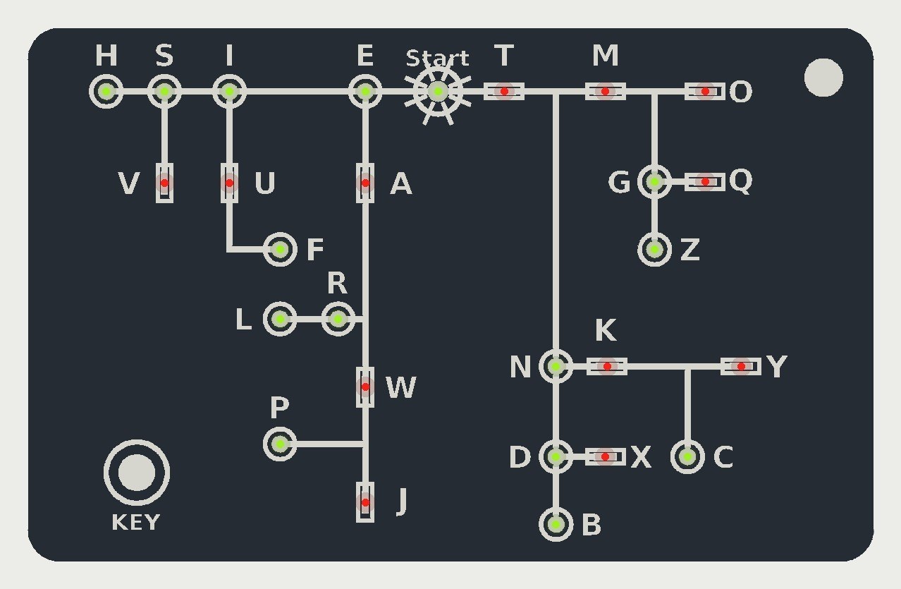
The pocket Morse decoder with no circuit board to order. A 3D-printed card the size of a bank card carries Dave Nathanson's decoding chart engraved in its face, with an SMD LED behind a window at every letter. Press the key short for a dot and long for a dash, and the letter you have reached lights.
Everything inside is hand-wired with enamelled copper wire to an Arduino Pro Mini, running on one CR2032 coin cell. The design has not been built yet.
Avançado
About 1 day, plus printing
Instruções
1
1
LED current and keying speed
LED current and keying speed
A carregar o notebook Jupyter…
2
2
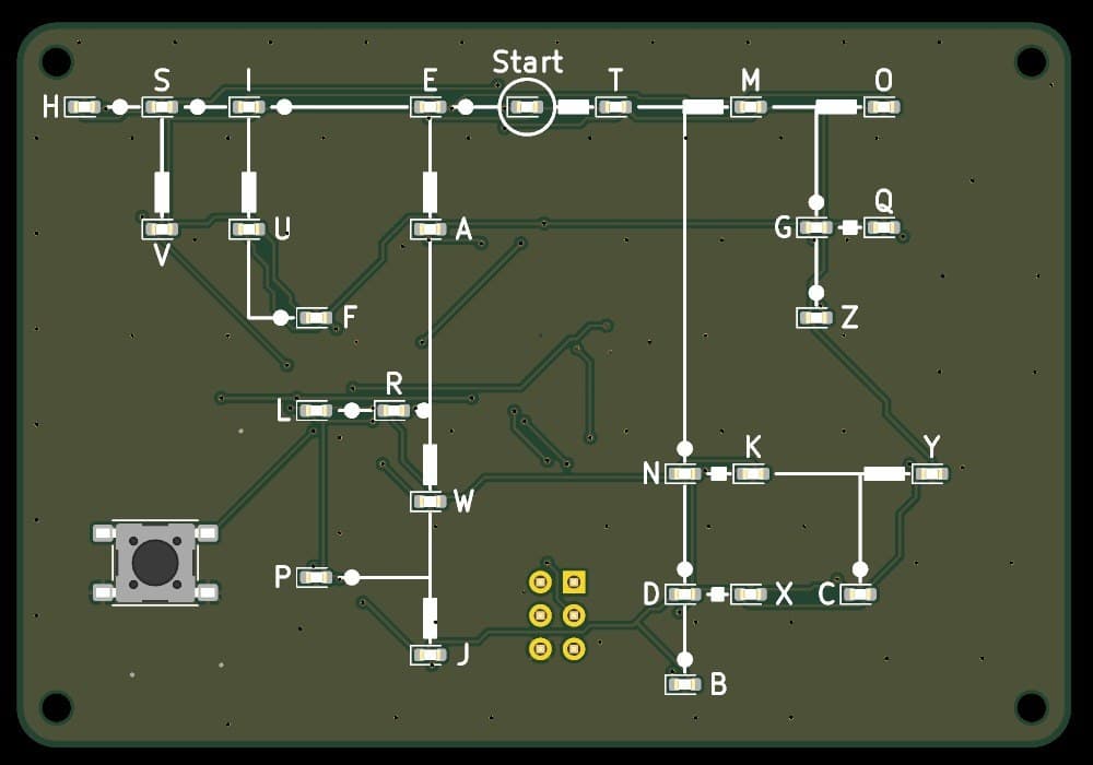
The same decoder on a circuit board
The same decoder on a circuit board
That version needs a board made to order. This one is printed and wired by hand.
3
3
Read the chart
Read the chart
Dave Nathanson (KG6ZJO) drew his decoding chart in 2010: "Start with your finger at "Start Here". Then move your finger to track the Morse dots & dashes. You will arrive at the correct letter!" On this card the LEDs do the tracking: yellow-green at the dots, red at the dashes.
4
4
Print the card body
Print the card body
The card, 85.6 x 54 x 7.5 mm, with the chart engraved 0.5 mm deep, a window and LED pocket at each letter, the key hole, four screw bosses and the key-ring hole. Print it face down on a smooth bed: PLA, 0.12 mm layers, no supports.
5
5
Print the lid
Print the lid
The 1.2 mm back lid with four countersunk screw holes and the credit and instructions engraved. PLA, 0.12 mm layers, engraved side down.
6
6
Fit the LEDs
Fit the LEDs
Press a 1206 LED into each pocket from the back, lens towards the window: yellow-green at the 14 dot rings and at Start, red at the 12 dash marks. Note each LED's cathode mark, then fix it with a tiny drop of glue at its edge, keeping the pads clean.
Materiais para este passo:
 LED de chip27 peças
 Cola instantânea (cianoacrilato)1 peça
Ferramentas necessárias:
 Pinça de pontas finas
 Lupa
 Multímetro
7
7
Wiring table
Wiring table
The 27 LEDs share six lines, D3 to D8, each LED between two of them. Wire each LED's + (anode) and - (cathode) pad to the lines below; the firmware expects exactly this.
| LED | Code | Colour | + (anode) to | - (cathode) to |
|---|---|---|---|---|
| Start | (none) | yellow-green | D3 | D4 |
| T | - | red | D4 | D3 |
| E | . | yellow-green | D4 | D5 |
| M | -- | red | D5 | D4 |
| N | -. | yellow-green | D5 | D6 |
| A | .- | red | D6 | D5 |
| I | .. | yellow-green | D6 | D7 |
| O | --- | red | D7 | D6 |
| G | --. | yellow-green | D7 | D8 |
| K | -.- | red | D8 | D7 |
| D | -.. | yellow-green | D3 | D5 |
| W | .-- | red | D4 | D6 |
| R | .-. | yellow-green | D5 | D3 |
| U | ..- | red | D5 | D7 |
| S | ... | yellow-green | D6 | D4 |
| Q | --.- | red | D6 | D8 |
| Z | --.. | yellow-green | D7 | D5 |
| Y | -.-- | red | D8 | D6 |
| C | -.-. | yellow-green | D3 | D6 |
| X | -..- | red | D4 | D7 |
| B | -... | yellow-green | D5 | D8 |
| J | .--- | red | D6 | D3 |
| P | .--. | yellow-green | D7 | D4 |
| L | .-.. | yellow-green | D8 | D5 |
| F | ..-. | yellow-green | D3 | D7 |
| V | ...- | red | D4 | D8 |
| H | .... | yellow-green | D7 | D3 |
8
8
Wire the card
Wire the card
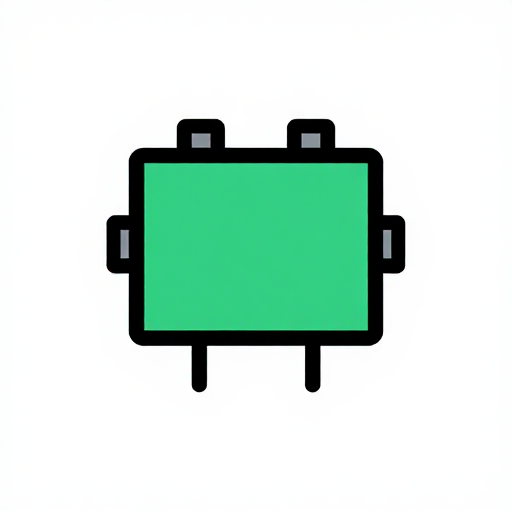
Remove the Pro Mini's power LED. Solder a 150 Ω resistor to each of D3-D8 and run a 0.2 mm solderable enamelled wire from each resistor round the cavity as that line's bus. Solder short wires from every LED pad to its bus, as the wiring table says; the iron strips the enamel. Wire the key between D2 and GND, and the cell holder's + to VCC and - to GND. Check every LED with the meter's diode test.
Materiais para este passo:
 Placa microcontroladora1 peça
 Resistência6 peças
 Botão de pressão1 peça
 Suporte de pilhas1 peça
 Fio de cobre esmaltado1 peça
 Fio de solda1 peça
Ferramentas necessárias:
 Ferro de soldarPinça de pontas finas
 FluxoLupaMultímetro
9
9
The firmware
The firmware
morse_card.ino: every timing is a named constant at the top. Board in the Arduino IDE: Arduino Pro or Pro Mini, ATmega328P (3.3V, 8 MHz).
morse_card.inoarduino
10
10
Upload
Upload
Take the cell out. Connect a 3.3 V USB-to-serial adapter to the Pro Mini's programming pins, choose Arduino Pro or Pro Mini, ATmega328P (3.3V, 8 MHz), and upload. Start lights; key E (one short press) and E lights.
Ferramentas necessárias:
 Adaptador USB-série
 Computador com o IDE Arduino
11
11
Close the card
Close the card
Glue the key into its hole, plunger through the face. Stick the Pro Mini and the cell holder to the lid's inside with double-sided tape, leaving the wires some slack, put a CR2032 in, and screw the lid on with four M2 x 6 self-tapping screws.
Materiais para este passo:
Cola instantânea (cianoacrilato)1 peça Fita de dupla face1 peça
 Parafuso autoatarraxante4 peças
 Pilha de botão CR20321 peça
 Filamento de PLA1 peça
Ferramentas necessárias:
 Impressora 3D de filamento (FDM)
 Conjunto de chaves de fendas de precisão
12
12
The build in 3D
The build in 3D
FreeCAD model of the card: the body with its engraved chart and LED windows, the lid, and the space taken by the Pro Mini, cell holder, key and screws, checked for clashes.
13
13
Troubleshooting
Troubleshooting
Printed Morse card troubleshooting.
Flow
Loading...
14
14
History and honest limits
History and honest limits
The chart is **Dave Nathanson**'s (KG6ZJO), drawn in 2010 and shared as copyleft. The letter codes are ITU-R M.1677-1's. The card, its sizes, parts, wiring and timings are ours. The model was checked for clashes and the firmware compiles with all 26 codes checked against ITU, but the card has not been printed, wired or tested.
Materiais
12- 27 peçasReferência
- Referência
- 1 peçaReferência
- 6 peçasReferência
- Referência
- Referência
- 1 peçaReferência
- 1 peçaReferência
- 1 peçaReferência
- 4 peçasReferência
- 1 peçaReferência
- 1 peçaReferência
Ferramentas necessárias
9- Referência
- Referência
- Referência
- 2 vendors sell this, none ship to you yetReferência
- Referência
- 3 vendors sell this, none ship to you yetReferência
- Referência
- Referência
- Referência
Ficheiros de design
3Este projeto faz
Blueprints relacionados
Estes blueprints compartilham conhecimento — técnicas, materiais ou princípios

CC0 Domínio Público
Este blueprint é liberado sob CC0. Você é livre para copiar, modificar, distribuir e usar este trabalho para qualquer finalidade, sem pedir permissão.
Apoie o Maker comprando produtos através do Blueprint, onde ele ganha uma Comissão Maker definida pelos vendedores, ou crie uma nova versão deste Blueprint e inclua-o como conexão no seu próprio Blueprint para compartilhar receita.