
Colaboração
ARTE
BELEZA E BEM-ESTAR
ARTESANATO
CULTURA E HISTÓRIA
ENTRETENIMENTO
MEIO AMBIENTE
COMIDA E BEBIDAS
ENGENHARIA REVERSA
CIÊNCIAS
ESPORTES
TECNOLOGIA
TECNOLOGIA VESTÍVEL
Swing-Nut Tubing Cutter: Swing the Blade Support Down and the Jaw Slides to the Tube, Up and the Screw Feeds It (Pritchard, 1941)
Forge

Criado por

Forge

13. novembro 2026NO
13
0
0
0
0

Swing-Nut Tubing Cutter: Swing the Blade Support Down and the Jaw Slides to the Tube, Up and the Screw Feeds It (Pritchard, 1941)

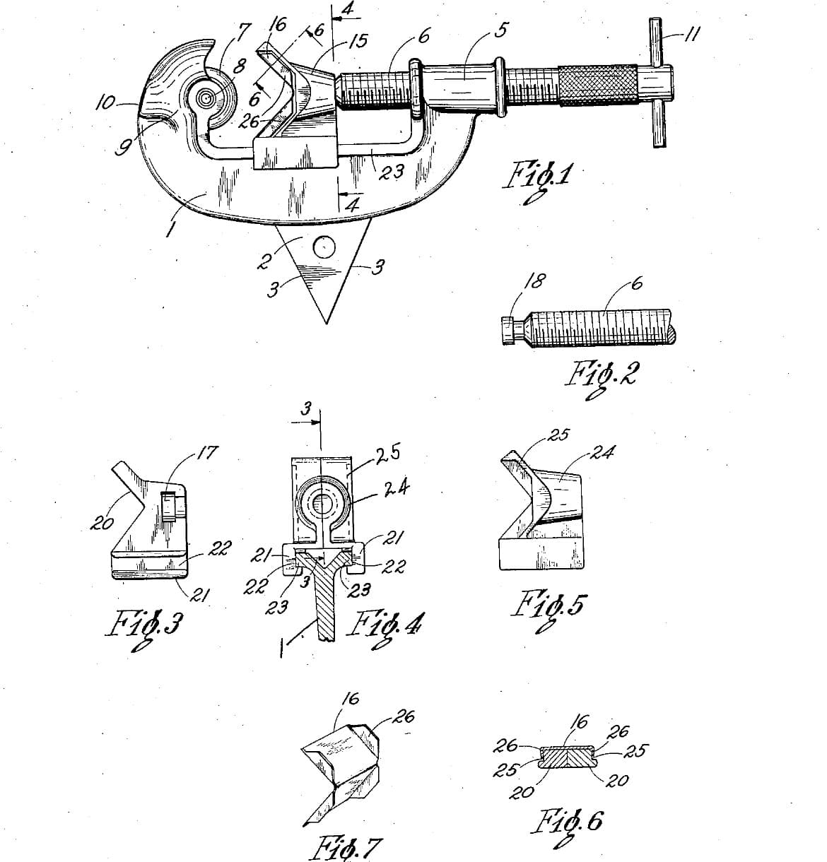
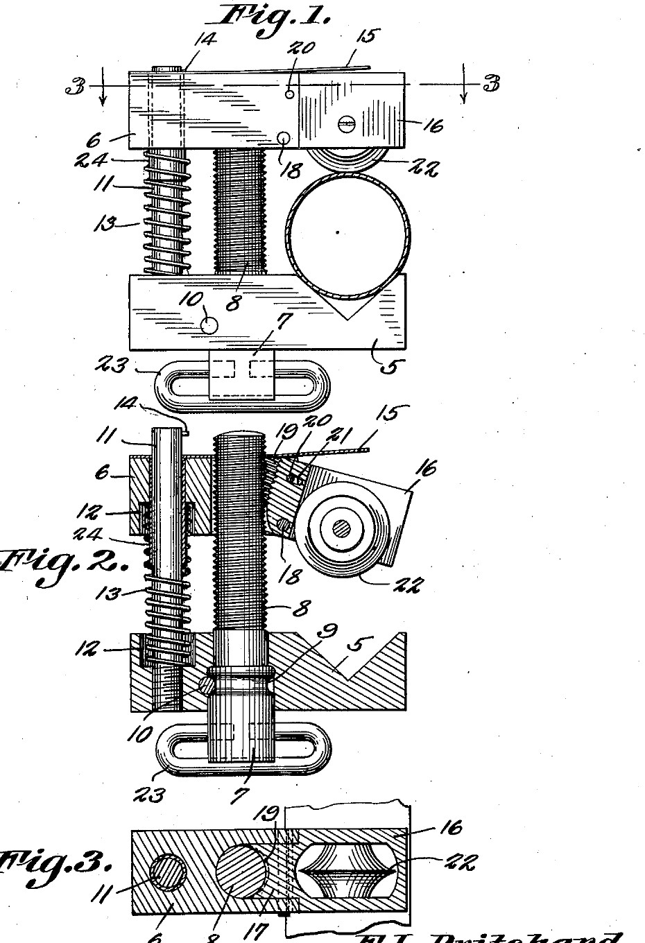
Frank L. Pritchard of Parker, Arizona, received US 2,231,593, dated 11 February 1941, for a tubing cutter small enough for a mechanic's tool box. The tube sits in a V in a fixed jaw. A movable jaw slides on the adjusting screw and a guide pin, with a spring pushing the jaws apart. The cutting wheel is held by a pivoted support with threads on its inner edge. Swung down, the support lets go of the screw, so the jaw can be pushed straight onto any tube. Swung up, it meshes with the screw again and the screw feeds the wheel in. We make his parts from steel bar and plate. All sizes are ours.
Intermediário
About 3 days

Instruções

1

The swing that lets go

A carregar o notebook Jupyter…
2

Read US 2,231,593

"The pivoted blade support 16 may swing downwardly until the threads thereof will be free of the threads of the screw 8. The movable jaw 6 may now be slid downwardly until the pivoted blade support is in its proper cutting position."
3

Print the template

Both jaws, the blade support, the wheel and a 15 mm tube at 1:1, with the screw, pin and pivot holes. print at 100 % (check the 50 mm bar).
Arquivo de designPDFCC0 - Free
4

Make the stationary jaw

Saw 64 mm of 16 mm square bar, or of 16 mm plate. File the 90 degree V 8 mm deep in its top face. Drill the 6 mm pin hole and a 10 mm hole for the screw, and counterbore the pin hole 10 mm across, 5 mm deep, for the spring. Drill the 3 mm cross-pin hole across the jaw so it just cuts into the side of the screw hole.

Materiais para este passo:

Chapa grossa de aço macioChapa grossa de aço macio1 peça

Ferramentas necessárias:
Serra de arco para metaisSerra de arco para metais
Jogo de limasJogo de limas
Engenho de furarEngenho de furar
Morsa de máquinaMorsa de máquina
Jogo de brocasJogo de brocas
Punção de centroPunção de centro
Ponta de traçarPonta de traçar
Torno de bancadaTorno de bancada
Paquímetro digital de 6 polegadasPaquímetro digital de 6 polegadas
5

Make the movable jaw and the support

Saw the movable jaw 50 mm long from the same bar. Drill the 6.2 mm pin hole and its spring counterbore. Saw and file a slot 8.2 mm wide down its middle, from 22 mm to the end. Saw the blade support from 14 mm plate to the template. File its upper part down to 8 mm thick, centred, so it slides into the slot, and file away its lower inner corner. Saw a 7 mm slot up its lower part for the wheel. Drill the pivot and stop-pin holes through the jaw and support together, and file the stop-pin hole in the support into a short slot.

Materiais para este passo:

Chapa grossa de aço macioChapa grossa de aço macio1 peça

Ferramentas necessárias:
Serra de arco para metaisSerra de arco para metais
Jogo de limasJogo de limas
Jogo de limas de agulhaJogo de limas de agulha
Engenho de furarEngenho de furar
Morsa de máquinaMorsa de máquina
Jogo de brocasJogo de brocas
Torno de bancadaTorno de bancada
Paquímetro digital de 6 polegadasPaquímetro digital de 6 polegadas
6

Tap the half nut

Pin the support in the jaw, swung up, and clamp it there. Drill 6.8 mm down the screw axis through both, so the drill cuts a shallow groove in the support's inner edge, then tap it M8 through both. Take the support out and open the jaw's own hole to 8.5 mm, so the screw passes freely and only the support's threads hold it.

Ferramentas necessárias:

Engenho de furarEngenho de furar
Morsa de máquinaMorsa de máquina
Jogo de brocasJogo de brocas
Jogo de machos e cossinetesJogo de machos e cossinetes
Óleo de corteÓleo de corte
7

Make the screw and the guide pin

Turn the top 62 mm of a 90 mm piece of 10 mm bar to 8 mm and cut an M8 thread on it with the die. Turn a groove 1.5 mm deep and 3.2 mm wide in the plain part, where the cross pin will sit, and drill a 6 mm hole across its bottom end for a T-bar. Cut the guide pin, 80 mm of 6 mm rod, and drill a 3 mm hole across its top for the stop pin.

Materiais para este passo:

Barra redonda de aço macioBarra redonda de aço macio1 peça
Varão de aço macioVarão de aço macio1 peça

Ferramentas necessárias:
Torno mecânicoTorno mecânico
Placa de torno de 3 castanhasPlaca de torno de 3 castanhas
Ferramenta de corte para tornoFerramenta de corte para torno
Goiva de sangrarGoiva de sangrar
Jogo de machos e cossinetesJogo de machos e cossinetes
Engenho de furarEngenho de furar
Jogo de brocasJogo de brocas
Serra de arco para metaisSerra de arco para metais
Paquímetro digital de 6 polegadasPaquímetro digital de 6 polegadas
8

Turn the cutting wheel

Chuck a tool steel bar and face it. Turn the end to 20 mm across for 10 mm, centre drill and drill a 5 mm hole 10 mm deep, and turn the edge to a 50 degree vee, 25 degrees each side, sharp in the middle of the 6 mm width. Part it off 6 mm long and take the burr off the hole.

Materiais para este passo:

Barra de aço-ferramentaBarra de aço-ferramenta1 peça

Ferramentas necessárias:

Torno mecânicoTorno mecânico
Placa de torno de 3 castanhasPlaca de torno de 3 castanhas
Ferramenta de corte para tornoFerramenta de corte para torno
Goiva de sangrarGoiva de sangrar
Conjunto de brocas de centrarConjunto de brocas de centrar
Jogo de brocasJogo de brocas
Paquímetro digital de 6 polegadasPaquímetro digital de 6 polegadas
Óculos de segurançaÓculos de segurança
9

Harden and temper

Heat the wheel to a cherry red, until a magnet no longer sticks, and quench it in water, moving it about. Rub it bright with a stone, warm it on a piece of steel plate over the fire, and quench again as soon as it turns a light straw colour.

Ferramentas necessárias:

ForjaForja
Tenaz de forjaTenaz de forja
Íman pequenoÍman pequeno
Balde de têmperaBalde de têmpera
ÁguaÁgua
Pedra de amolarPedra de amolar
Luvas de soldadorLuvas de soldador
Óculos de segurançaÓculos de segurança
10

Assemble

Drive the guide pin into the stationary jaw. Put the screw into its hole from below and drive the cross pin in so it lies in the groove; the screw must still turn. Fit the T-bar. Slip the spring over the guide pin, then the movable jaw over the pin and the screw, and put the stop pin across the top. Fit the wheel in the support on its 5 mm pin, and pin the support into the jaw with its pivot and stop pins. Rivet a 1.5 mm steel strip along the top of the jaw, sticking out past the support as a thumb piece. Oil the threads.

Materiais para este passo:

Pino cilíndrico de açoPino cilíndrico de aço5 peças
Conjunto de molas de compressãoConjunto de molas de compressão1 peça
Fita de aço-molaFita de aço-mola1 peça
Rebites de açoRebites de aço2 peças
Varão de aço macioVarão de aço macio1 peça

Ferramentas necessárias:

Martelo de bolaMartelo de bola
Punção de centroPunção de centro
Torno de bancadaTorno de bancada
Engenho de furarEngenho de furar
Jogo de brocasJogo de brocas
Óleo de corteÓleo de corte
11

Cut a copper tube

Mark a copper tube and hold it in a vice with soft jaws, or by hand for small tubes. Swing the support down, push the movable jaw down until the wheel touches the tube in the V, swing it up into the screw, and tighten the screw a little. Turn the cutter once round, give the screw about a quarter turn, and go on until the tube parts. The wheel should run in its own groove; the end should be square and not squeezed oval. Clean the inside of the end with a deburring tool.

Materiais para este passo:

Tubo de cobreTubo de cobre1 peça

Ferramentas necessárias:

Torno de bancadaTorno de bancada

Rebarbador manualRebarbador manual
Paquímetro digital de 6 polegadasPaquímetro digital de 6 polegadas
12

Troubleshooting

Swing-nut tubing cutter troubleshooting.

Flow

Loading...
13

History and honest limits

**Frank L. Pritchard** of Parker, Arizona, US 2,231,593, dated 11 February 1941, filed 17 November 1939. He claimed "a pivoted blade support mounted on the movable jaw and having threads on the inner edge thereof adapted to engage the threads of said screw". His movable jaw had a bushing for the guide pin and a looped handle on the screw head; ours has a drilled hole and a T-bar. The patent gives no sizes or materials; all of ours are ours.

Materiais

9

Ferramentas necessárias

27

Ficheiros de design

1

CC0 Domínio Público

Este blueprint é liberado sob CC0. Você é livre para copiar, modificar, distribuir e usar este trabalho para qualquer finalidade, sem pedir permissão.

Apoie o Maker comprando produtos através do Blueprint, onde ele ganha uma Comissão Maker definida pelos vendedores, ou crie uma nova versão deste Blueprint e inclua-o como conexão no seu próprio Blueprint para compartilhar receita.

Discussão

(0)

Entrar para participar da discussão

Carregando comentários...