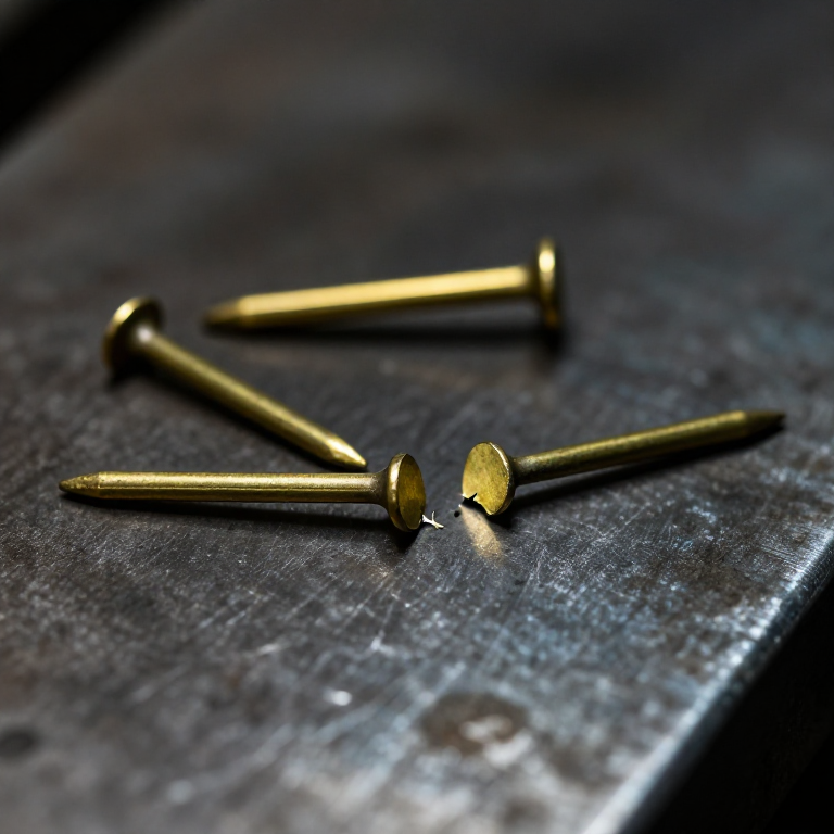


Shear Pin Coupling
说明
Compute the pin size before making anything
Compute the pin size before making anything
This is the one protective device you can calculate rather than calibrate.
- Choose the torque you want it to break at, and the pin radius from the shaft centre — say 25 mm.
- Force on the pin = torque ÷ radius.
- The pin is in DOUBLE shear, so each of its two shear planes carries half that force.
- Required area per plane = force per plane ÷ the material's shear strength.
- Convert area to a diameter, and write down the number.
Double shear is the detail people miss. A pin passing through a hub and a shaft is cut across at two places, so it carries twice what a single-shear pin of the same diameter would. Forget it and your pin breaks at half the torque you intended.
Brass and aluminium are the usual choices because their shear strengths are modest and reasonably consistent, and because they fail cleanly rather than deforming and hanging on. Mild steel makes a poor shear pin — it yields and stretches first, so the break torque is vague.此步骤所需材料:
 坐标纸1 pad
所需工具:
 6 英寸数显卡尺
Make the two hubs and drill them together
Make the two hubs and drill them together
The pin hole must line up perfectly, so drill both parts as one.
- Cut two hubs from 25 mm aluminium round bar, each 30 mm long, bored 8.0 mm.
- Make one a spigot that fits inside the other, so they are concentric but free to rotate relative to each other.
- Assemble them and clamp.
- Drill the pin hole THROUGH BOTH at once, radially, at 4.0 mm.
- Deburr both holes carefully.
Drilling together is what makes the pin a shear element rather than a bending one. Misaligned holes force the pin to bend as it takes up the offset, and a bent pin fails at an unpredictable torque — usually much lower than calculated, which destroys the whole point of a calculable device.
Deburring matters more than usual here: a burr in the hole is a stress raiser that starts the fracture early, and this is a component whose failure point is meant to be exact.此步骤所需材料:
 铝圆棒1 个
所需工具:
 钢锯弓配锯条
 台虎钳
台虎钳 充电式电钻
充电式电钻 钻头套装
钻头套装 锉刀套装6 英寸数显卡尺
 中心冲
中心冲Make a set of pins in two materials
Make a set of pins in two materials
Several of each, identical, because you are going to destroy them.
- Cut six pins from 4 mm brass round bar and six from 4 mm aluminium.
- Face both ends of each square and deburr.
- Measure every pin with the caliper and discard any that differ.
- Label the two sets clearly and keep them separate.
Modern build spec (derived). Brass has roughly twice the shear strength of soft aluminium, so the same 4 mm pin gives two clearly different protection levels from one coupling — which is a neat way to change the setting without changing any dimension.
Keep the sets separate and labelled. A brass pin fitted where an aluminium one was intended doubles the protection torque, and there is no way to tell by looking once it is in the hole. This is a real failure mode in the field, not a hypothetical one.此步骤所需材料:
 黄铜圆棒1 个铝圆棒1 个
所需工具:
钢锯弓配锯条锉刀套装6 英寸数显卡尺台虎钳Break them, and compare with your calculation
Break them, and compare with your calculation
Prediction against measurement — the whole reason to build this.
- Clamp one hub, fit an aluminium pin, and load the other hub through a lever arm of known length.
- Increase the load until the pin shears. Record the force and compute the torque.
- Repeat with two more aluminium pins and average.
- Repeat the whole set with brass pins.
- Compare both averages against your step 1 calculation.
所需工具:
台虎钳6 英寸数显卡尺 内六角扳手组
The stronger-pin temptation, and history
The stronger-pin temptation, and history
The classic failure is human, not mechanical. A machine keeps shearing pins, so somebody fits a stronger one — a steel bolt instead of a brass pin. The shearing stops, and the next overload breaks a gearbox, a shaft or a casting instead. The shear pin did not fail; it was overruled. This is why good practice keeps correct pins with the machine, and why some designs make it physically awkward to fit the wrong thing.
Where shear pins are standard: snow blower augers, agricultural implements, boat propellers, and light machinery generally. In each case the overload is a sudden shock — a rock, a frozen lump, a submerged log — which is exactly the case a friction limiter handles badly, because the inertia spike passes through before the plates can slip.
Against the torque limiter, plainly: the limiter is resettable, adjustable and forgiving, but its trip torque drifts with wear and contamination and it cannot stop a sharp shock. The shear pin is exact, computable, immune to drift, and useless until somebody replaces it. Choose by asking how often the overload happens and how bad an unnoticed drift would be.
The wider idea: both are deliberate weak links, and the electrical fuse is the same thought in another domain — a cheap, calculable, sacrificial element that fails so that expensive things do not. Recognising when to design one in is a mark of an engineer who has thought about what happens when the machine meets the real world.

CC0 公共领域
此蓝图以 CC0 协议发布。你可以自由复制、修改、分发和使用此作品,无需征得许可。
通过购买蓝图中的产品支持创客,他们将获得 创客佣金 (由供应商设定),或创建此蓝图的新版本并将其作为连接包含在你自己的蓝图中以分享收入。