Colaboración
ARTE
BELLEZA Y BIENESTAR
ARTESANÍA
CULTURA E HISTORIA
ENTRETENIMIENTO
MEDIO AMBIENTE
COMIDA Y BEBIDAS
INGENIERÍA INVERSA
CIENCIAS
DEPORTES
TECNOLOGÍA
TECNOLOGÍA VESTIBLE
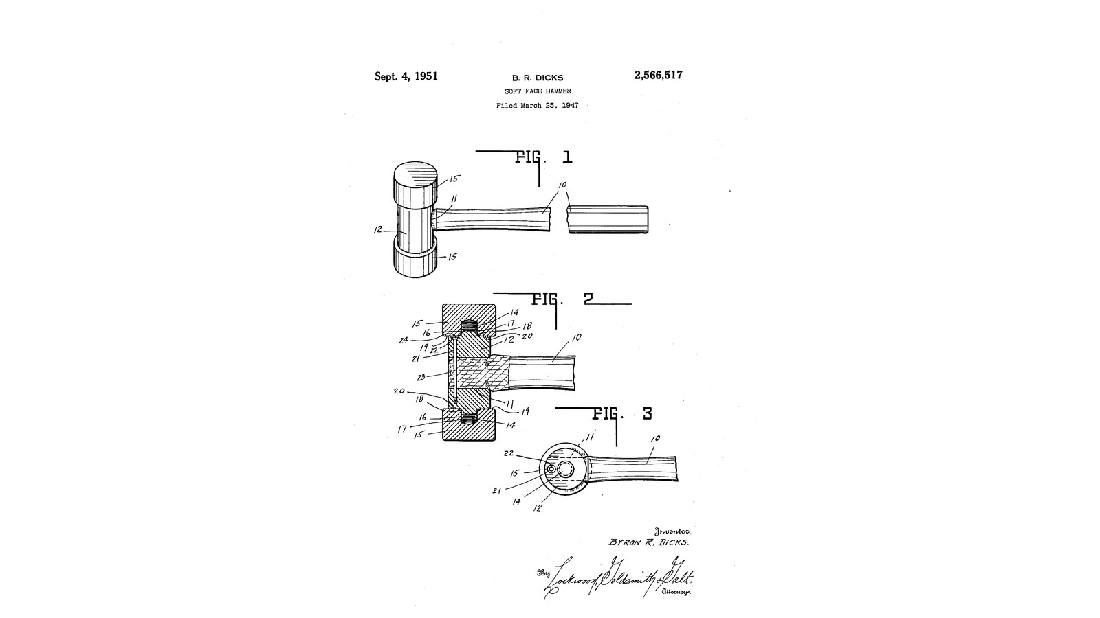

Threaded-Stud Rubber-Head Hammer: Heads Screw Onto the Body's Own Studs and Lock the Handle's Nail In (Dicks, 1951)
Byron R. Dicks of Lebanon, Indiana, received US 2,566,517, dated 4 September 1951, for a hammer made cheaply from bar stock with heads of any material. Each end of the cylindrical body has a threaded stud turned in one piece with it. Each head has a threaded socket chamfered at its mouth, so it bears on the body's flat end face in a true ring and the stud only connects. A nail driven down a bore beside the stud locks the handle. Its head sits in a counterbore, and the screwed-on head keeps it from ever coming out.
We give it two rubber heads, from his list of materials. The sizes are ours.
Intermedio
About 2 days
Instrucciones
1
1
Where the locking nail goes
Where the locking nail goes
Cargando el cuaderno de Jupyter…
2
2
Read US 2,566,517
Read US 2,566,517
"The nail when driven home obviously forms its own hole through the handle." "Obviously application of the head 15 retains the nail against loss if the same ever became somewhat loose in the handle."
3
3
Turn the body 12
Turn the body 12
From 38 mm steel round bar turn a body 80 mm long between end faces cut truly square, with a stud 14 16 mm across and 18 mm long standing out of each end; cut M16 threads on them with the die. Drill a 20 mm eye 11 through the middle, square to the axis, in a V-block, and flare its ends a little with a half-round file.
Materiales para este paso:
 Barra redonda de acero dulce1 pieza
 Aceite de corte1 pieza
Herramientas necesarias:
 Torno de metal
 Plato de torno de 3 mordazas
 Herramienta de corte para torno
 Gubia de tronzar
 Juego de machos y terrajas
 Portaterrajas
 Tornillo de banco
 Taladro de columna
 Bloque en V
 Juego de brocas
 Juego de limas
 Calibre digital de 6 pulgadas
 Gafas de seguridad
4
4
Bore for the locking nail 21
Bore for the locking nail 21
Scribe a line across one end face along the eye's direction. Centre-punch it 13 mm from the centre and drill 4.2 mm parallel to the axis, down into the eye, and counterbore the mouth 7 mm across and 4 mm deep for the nail's head.
Herramientas necesarias:
 Punta de trazar
 GraneteTaladro de columnaBloque en VJuego de brocasCalibre digital de 6 pulgadas
5
5
Rubber heads 15
Rubber heads 15
For each head saw an M16 coupling nut to 25 mm and chamfer one end's thread 1 mm with a countersink: the socket 16 with its chamfered mouth 18. Cut 4 mm rubber discs 50 mm across: seven with a hole just round the nut and five solid. Bond them up round the nut with contact cement, the chamfered end flush with the head's inner face, and the solid discs at the striking face; clamp overnight and trim round.
Materiales para este paso:
 Tuerca hexagonal2 piezas
 Plancha de caucho natural1 pieza
 Cemento de contacto1 pieza
Herramientas necesarias:
 Sierra para metalesTornillo de banco
 Juego de brocas avellanadorasTaladro de columna
 Brújula
 Cúter de precisión
 Sargento
6
6
Handle, nail and heads
Handle, nail and heads
Turn an ash handle 300 mm long to drive tight into the eye. Drive it home, then drive a 4 mm nail 23 down the bore through the handle until its head sits in the counterbore below the end face. Screw the rubber heads onto the studs until each bears hard on its end face.
Materiales para este paso:
 Tabla de madera dura1 pieza
 Clavos1 pieza
Herramientas necesarias:
 Torno de madera
 Juego de herramientas de torno (HSS)
 Martillo de bola
7
7
Troubleshooting
Troubleshooting
Threaded-stud hammer troubleshooting.
Flow
Loading...
8
8
History and honest limits
History and honest limits
**Byron R. Dicks** of Lebanon, Indiana, US 2,566,517, dated 4 September 1951, filed 25 March 1947. He claimed a cylindrical body "having flat faces at both ends disposed at true right angles to the axis", "threaded extensions integral with said body", detachable heads with threaded sockets "in face to face contact" with the body, a transverse handle opening, a longitudinal bore offset from the extensions through it, and "a safety pin" in the bore sealed in by the heads. His heads were turned from bar or made of any of the materials he lists, rubber among them; ours are rubber discs bonded round a threaded steel insert. He gives no sizes; every size here is ours.
Materiales
7- 1 piezaMarcador de posición
- 1 piezaMarcador de posición
- 2 piezasMarcador de posición
- 1 piezaMarcador de posición
- 1 piezaMarcador de posición
- 1 piezaMarcador de posición
- 1 piezaMarcador de posición
Herramientas requeridas
23- Marcador de posición
- Marcador de posición
- Marcador de posición
- Marcador de posición
- Marcador de posición
- Marcador de posición
- Marcador de posición
- Marcador de posición
- Marcador de posición
- Marcador de posición
- Marcador de posición
- Marcador de posición
- Marcador de posición
- Marcador de posición
- Marcador de posición
- Marcador de posición
- Marcador de posición
- Marcador de posición
- Marcador de posición
- Marcador de posición
- Marcador de posición
- Marcador de posición
- Marcador de posición
Este plano hace

Blueprints relacionados
Estos blueprints comparten conocimiento — técnicas, materiales o principios
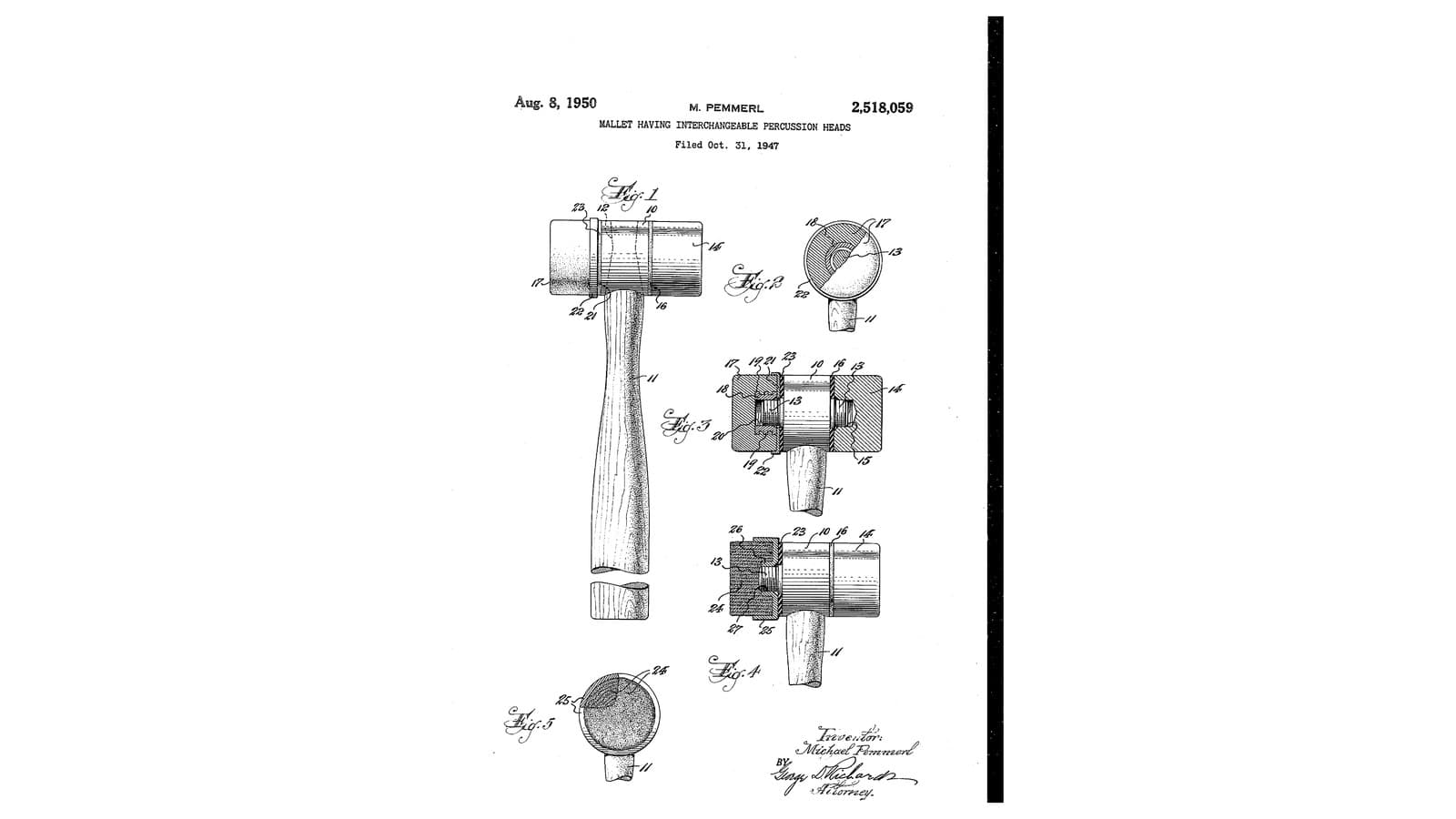
Screw-On Rubber Head Mallet: Rubber Members on Flanged Ferrules, Cupped and Cushioned on Steel Studs (Pemmerl, 1950)
por Forge
Trabajo en Metal
0
0
0
0
0
0
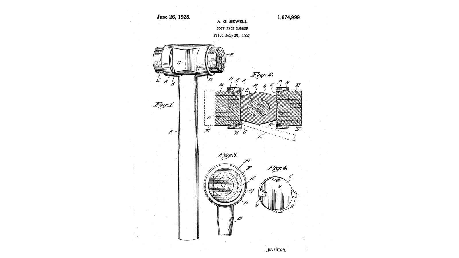
Renewable Rubber-Face Hammer: Rolled Faces Pressed Onto Pronged Discs, Driven Out Through a Notch When Worn (Sewell, 1928)
por Forge
Trabajo en Metal
0
0
0
0
0
0
CC0 Dominio público
Este Blueprint se publica bajo CC0. Eres libre de copiar, modificar, distribuir y usar este trabajo para cualquier propósito, sin pedir permiso.
Apoya al Maker comprando productos a través de su Blueprint, donde gana una Comisión del Maker establecida por los vendedores, o crea una nueva iteración de este Blueprint e inclúyela como conexión en tu propio Blueprint para compartir ingresos.