Collaboration
ART
BEAUTÉ ET BIEN-ÊTRE
ARTISANAT
CULTURE ET HISTOIRE
DIVERTISSEMENT
ENVIRONNEMENT
NOURRITURE ET BOISSONS
INGÉNIERIE INVERSE
SCIENCES
SPORTS
TECHNOLOGIE
TECHNOLOGIE PORTABLE
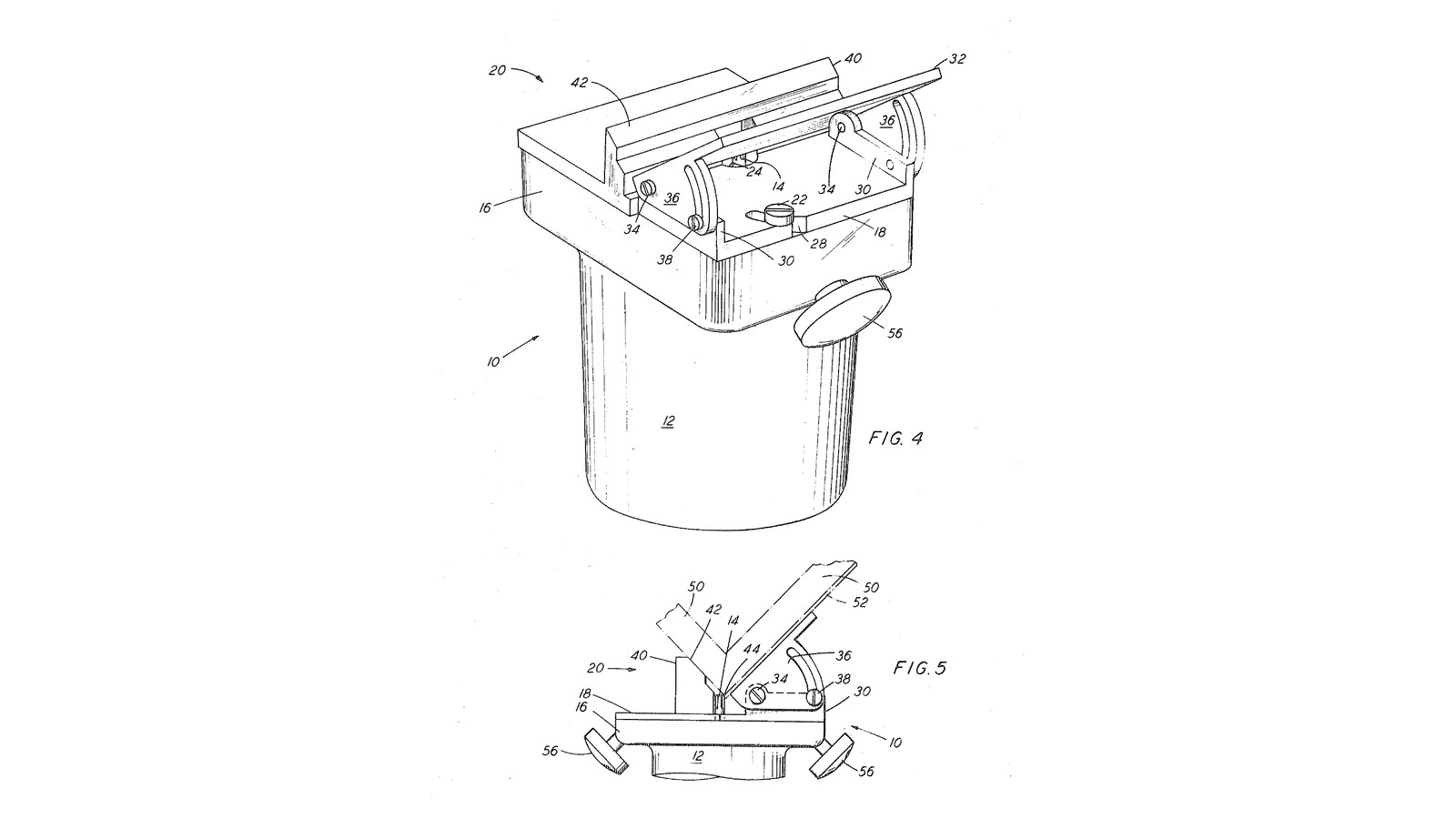


Laminate Bevel Trimmer: Two Pads at Right Angles Hold a Small Router at 45 Degrees on a Corner (Roche, 1971)
Edward Noland Roche of Cockeysville, Maryland, received US 3,628,579, dated 21 December 1971, for a small router that bevels plastic laminate in place. Laminate is usually trimmed after it is glued down, and a mitred corner meant mitring the wood underneath too. Roche's tool rides on the corner of the already-built carcass. A fixed pad with a 45 degree face sits on the top surface, a tilting pad sits on the side face, and the cutter between them bevels the laminate's edge inwards, exactly to the edge beneath it. The guide base swings slightly on a pivot to line the pad up with the cutter.
We print the motor unit, base and pads in PETG round a small DC motor. The 45 degrees is his; the other sizes are ours.
Avancé
About 2 days
Consignes
1
1
Why the substrate needs no mitre
Why the substrate needs no mitre
Chargement du notebook Jupyter…
2
2
Read US 3,628,579
Read US 3,628,579
"This pad 40 has a raised guide face 42 that slopes at a 45 degree plane which extended, coincides with the far edge of the cutting tool." "An inwardly sloping bevel 58 which exactly conforms with the edge of the substrate 50 results."
3
3
Print the motor unit
Print the motor unit
The motor unit 12: a tube for a 42 mm motor with the square faceplate 16 at its end, an 18 mm hole and two M4 holes for the motor, a hole to tap M4 for the pivot stud 26 and one to tap M5 for the adjusting screw 22, and two handle bosses. Print it faceplate down. PETG, 0.2 mm layers, 40 % infill, 5 walls.
4
4
Print the guide base
Print the guide base
The base 18: a flat plate with the clearance hole 24, the stud hole, the curved slot 28, the fixed pad 40 with its 45 degree face 42, and the two ears 30. Print it plate down. PETG, 0.2 mm layers, 40 % infill, 5 walls.
5
5
Print the adjustable pad
Print the adjustable pad
The pad 32 with its two cheeks 36, each with a hole for the pivot screw 34 and an arc slot for the locking screw 38. Print it plate down. PETG, 0.2 mm layers, 40 % infill, 5 walls.
6
6
Motor unit
Motor unit
Tap the faceplate's two holes M4 and M5. Fit the collet adapter on the motor, stand the motor in the tube with its face on the faceplate and the collet through the hole, screw it in with two M4 screws, and wire it through a toggle switch to the DC supply. Turn two hardwood knobs 56 and bolt them to the handle bosses.
Matériaux pour cette étape :
 Filament PETG1 pièce
 Moteur électrique1 pièce
 Adaptateur à pince pour arbre moteur1 pièce
 Vis à tête cylindrique à six pans creux2 pièces
 Interrupteur à levier1 pièce
 Fil de câblage1 pièce
 Gaine thermorétractable1 pièce
 Planche de bois dur1 pièce
 Assortiment de boulons à tête hexagonale2 pièces
 Écrou hexagonal2 pièces
Outils nécessaires :
 Imprimante 3D à filament (FDM)
 Jeu de tarauds et filières
 Tourne-à-gauche
 Alimentation en courant continu
 Fer à souder électrique
 Jeu de clés Allen
 Tour à bois
 Perceuse sans fil
 Jeu de forets
7
7
Guide base, pads and setting
Guide base, pads and setting
Fit a 1/4 inch straight bit in the collet. Lay the base on the faceplate, the cutter through its hole; screw an M4 screw through the corner hole into the faceplate as the pivot stud 26, and an M5 screw with a washer through the curved slot as the adjusting screw 22. Hold a straightedge on the fixed pad's sloping face, reaching past the cutter, and swing the base on its stud until the straightedge just touches the cutter's far edge; tighten the adjusting screw. Hang the adjustable pad on the ears with two M4 pivot screws 34 and two M4 locking screws 38 through its arc slots; set it square to the fixed pad's face for 90 degree corners and lock it.
Matériaux pour cette étape :
Vis à tête cylindrique à six pans creux6 pièces Rondelle plate3 pièces
Outils nécessaires :
 Coffret de fraises de défonceuseJeu de clés Allen
 Équerre combinée
 Rapporteur
8
8
Bevel a laminate edge
Bevel a laminate edge
Clamp a sheet temporarily to one face of the built carcass with its edge standing proud past the corner. Hold the tool by its knobs at 45 degrees, fixed pad on the top surface and adjustable pad on the side, switch on and run it along the edge until both pads bear on the work and the cutting stops: the laminate's edge is bevelled exactly to the corner. Take the sheet off, keep it for gluing, and do the next face.
Outils nécessaires :
 Serre-joint à pompe
 Lunettes de sécurité
9
9
Troubleshooting
Troubleshooting
Laminate trimmer troubleshooting.
Flow
Loading...
10
10
History and honest limits
History and honest limits
**Edward Noland Roche** of Cockeysville, Maryland, US 3,628,579, dated 21 December 1971, filed 18 November 1969. He claimed a laminate chamfering machine with a faceplate and cylindrical cutter, a guide base pivoted at one corner and locked through "a curved slot formed therein to the radius from said pivot means", pads on the base's two halves, and "a guide pad having a raised guide face sloping at a predetermined plane which extended coincides with the far edge of said cutting tool". He gives the 45 degree slope and no sizes; ours are printed PETG parts round a small DC motor, and we set the pad to the cutter with a straightedge rather than by a figure.
Matériaux
11- 1 pièceEspace réservé
- 1 pièceEspace réservé
- Espace réservé
- Espace réservé
- Espace réservé
- Espace réservé
- 1 pièceEspace réservé
- 1 pièceEspace réservé
- Espace réservé
- 2 piècesEspace réservé
- 3 piècesEspace réservé
Outils requis
14- Espace réservé
- Espace réservé
- Espace réservé
- Espace réservé
- Espace réservé
- Espace réservé
- Espace réservé
- 1 vendor sell this, none ship to you yetEspace réservé
- Espace réservé
- 1 vendor sell this, none ship to you yetEspace réservé
- Espace réservé
- Espace réservé
- Espace réservé
- Espace réservé
Fichiers de conception
3Ce plan fabrique

Blueprints liés
Ces blueprints partagent des connaissances — techniques, matériaux ou principes
CC0 Domaine public
Ce blueprint est publié sous CC0. Vous êtes libre de copier, modifier, distribuer et utiliser ce travail pour tout usage, sans demander la permission.
Soutenez le Maker en achetant des produits via son Blueprint où il perçoit une Commission Maker définie par les Vendeurs, ou créez une nouvelle itération de ce Blueprint et incluez-le comme connexion dans votre propre Blueprint pour partager les revenus.