ART
BEAUTÉ ET BIEN-ÊTRE
ARTISANAT
CULTURE ET HISTOIRE
DIVERTISSEMENT
ENVIRONNEMENT
NOURRITURE ET BOISSONS
INGÉNIERIE INVERSE
SCIENCES
SPORTS
TECHNOLOGIE
TECHNOLOGIE PORTABLE
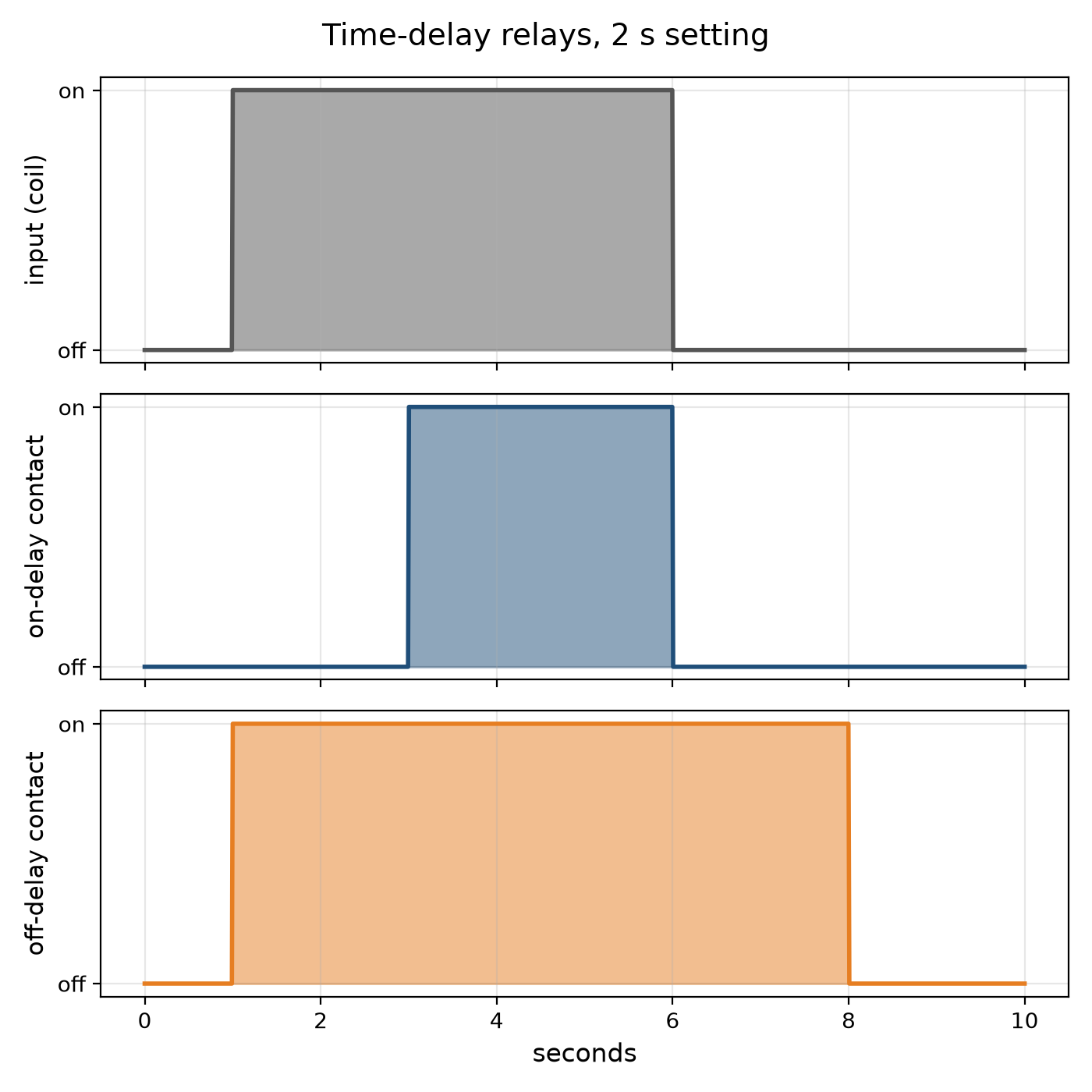
Youblob (generated from this blueprint's notebook) · CC0


The Time-Delay Relay: Switching a Set Time Later
Many control jobs need a pause: start the motor, wait until it is up to speed, then load it; stop the burner, then run the fan a little longer to clear the heat; light the stairway, and switch it off a few minutes later. The time-delay relay does it. An on-delay closes its contact a set time after it is energised; an off-delay keeps its contact closed a set time after it is de-energised.
The earliest timed their delay with a dashpot — a piston pushing air or oil through a small adjustable hole — or with a bimetal warmed by a heater. Electronic relays charge a capacitor through a resistor and switch when it reaches a threshold.
This rung works out an RC delay and why capacitor tolerance and leakage limit it, draws on- and off-delay timing, and builds an on-delay relay with a 555 timer.
Débutant
About 3 hours
Consignes
1
1
The RC delay and its limits
The RC delay and its limits
Chargement du notebook Jupyter…
2
2
Build a 555 on-delay relay
Build a 555 on-delay relay
On a breadboard wire a 555 as a monostable from a 9–12 V supply: pins 4 and 8 to the supply, pin 1 to 0 V, a resistor R from the supply to pins 6 and 7 joined, a capacitor C from pins 6 and 7 to 0 V, 10 nF from pin 5 to 0 V, and pin 2 (trigger) held high through 10 kΩ with a push button to 0 V.
Pin 3 goes high for 1.1 RC after the button is pressed. Drive an NPN transistor from pin 3 through 1 kΩ, with the relay coil between the supply and the collector and a diode across the coil, reversed, to catch the coil's kick. Wire an LED through the relay's contact.
Time the relay with a stopwatch for three values of R. Plot delay against R: a straight line whose slope is 1.1 C. Swap in a second capacitor of the same marked value and watch the delay change — its tolerance.
Matériaux pour cette étape :
 Circuit intégré minuteur NE5551 pièce
 Transistor NPN1 pièce
 Relais SPDT1 pièce
 Diode1 pièce
 Kit de condensateurs1 pièce
 Assortiment de résistances1 pièce
 Bouton-poussoir1 pièce
 LED 5 mm1 pièce
 Plaque d'essai1 pièce
 Fils de liaison1 pièce
 Relais temporisé1 pièce
Outils nécessaires :
 Alimentation en courant continu
 Multimètre
 Chronomètre
3
3
The relay it times
The relay it times
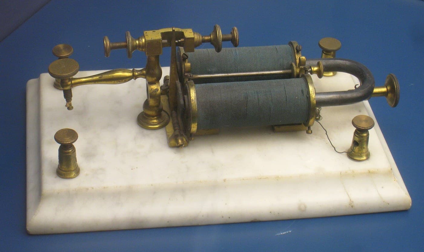
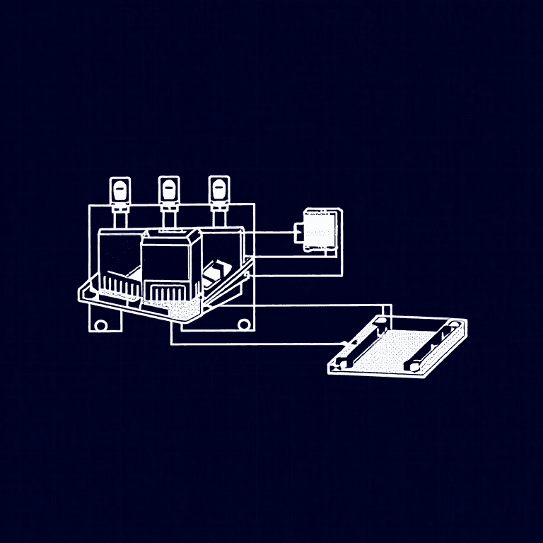
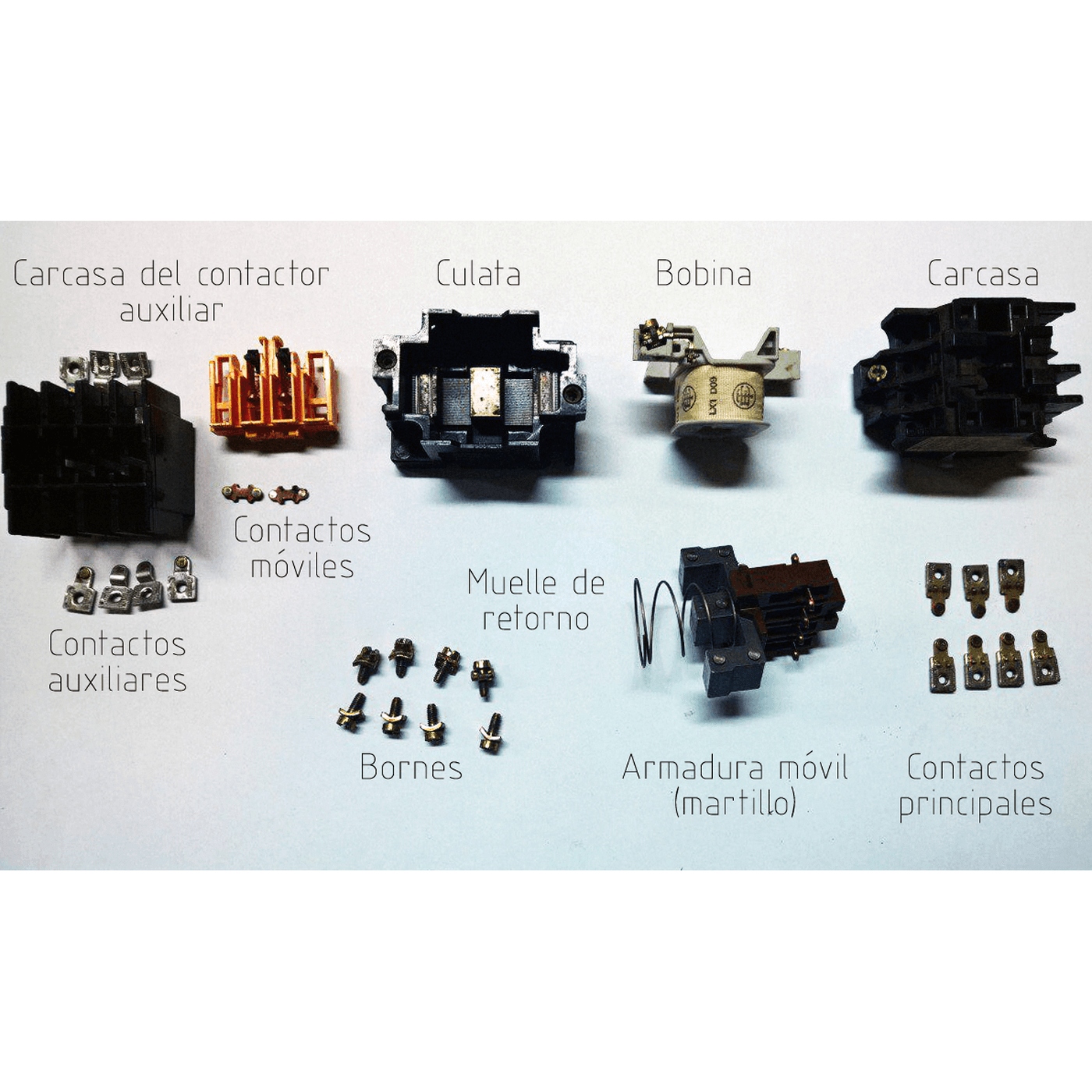
A time-delay relay is a relay with a clock in front of it. The embedded blueprint shows the electromagnetic relay it drives.
4
4
A timer that times wrong
A timer that times wrong
Time-delay relay faults.
Flow
Loading...
5
5
Context and honest limits
Context and honest limits
Pneumatic dashpot timers, thermal timers and motor-driven timers served machine and process control for decades; the 555 timer IC, introduced in 1972, made cheap electronic delays universal, and programmable controllers now provide timers in software.
**Honest limits.** An RC delay drifts with temperature and with the capacitor's age. For accurate long delays use a crystal-timed or counting timer. A relay switching mains loads must be wired and enclosed by someone qualified; the bench build stays at low voltage.
Matériaux
11- Espace réservé
- 1 pièceEspace réservé
- 1 pièceEspace réservé
- 1 pièceEspace réservé
- 1 pièceEspace réservé
- à partir de€4.96
- à partir de€0.45
- à partir de€8.29
- à partir de€1.41
- 1 pièceEspace réservé
Outils requis
3- Espace réservé
- Espace réservé
- Espace réservé
Blueprints liés
Ces blueprints partagent des connaissances — techniques, matériaux ou principes


CC0 Domaine public
Ce blueprint est publié sous CC0. Vous êtes libre de copier, modifier, distribuer et utiliser ce travail pour tout usage, sans demander la permission.
Soutenez le Maker en achetant des produits via son Blueprint où il perçoit une Commission Maker définie par les Vendeurs, ou créez une nouvelle itération de ce Blueprint et incluez-le comme connexion dans votre propre Blueprint pour partager les revenus.