コラボレーション
アート
美容とウェルネス
工芸
文化と歴史
エンターテインメント
環境
食品と飲料
リバースエンジニアリング
科学
スポーツ
テクノロジー
ウェアラブル
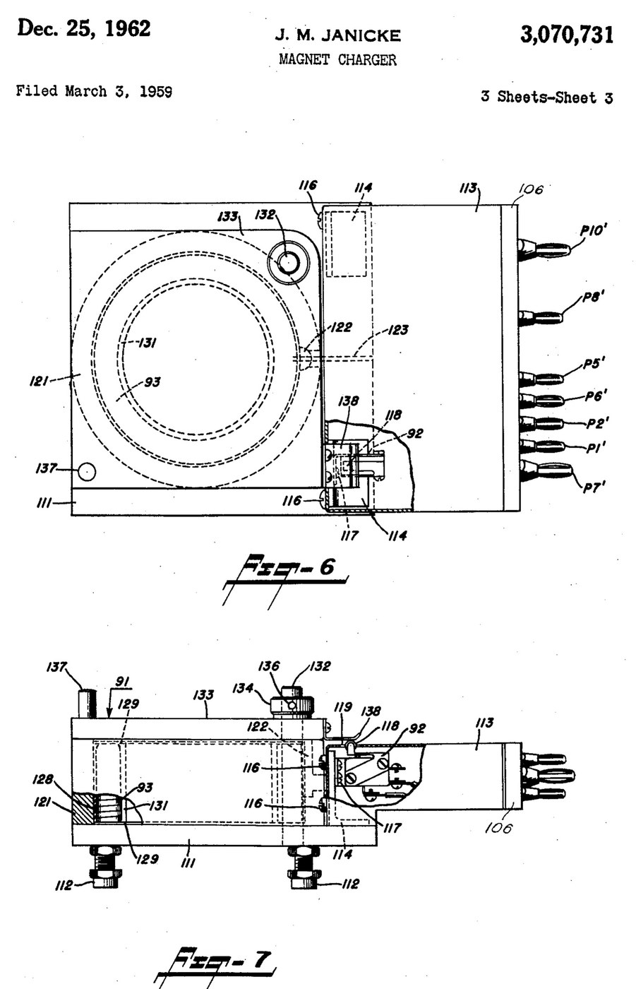


Magnetiser: Capacitor-Discharge Magnet Charger with a Wire-Wound Fixture (Janicke, US 3,070,731, 1962)
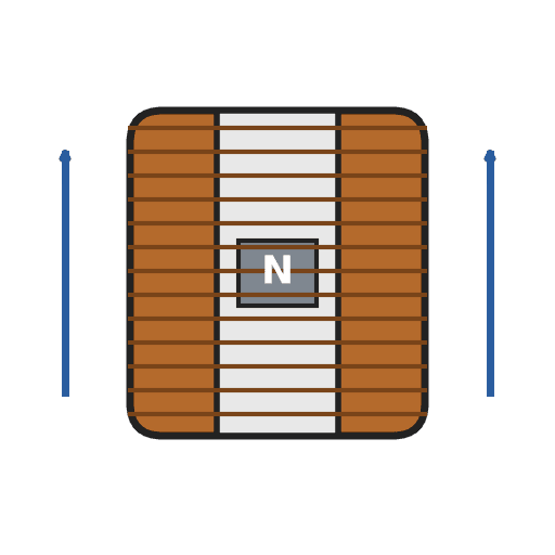
An impulse magnetiser. A capacitor is charged to a high voltage, then an ignitron dumps it all at once through a coil. The magnet sits inside the coil in a closed steel pot, so almost all of the flux goes through it.
Result: a magnet charger that magnetises rods, bars and blocks in one pulse, with an interlocked lid.
Source: J. M. Janicke, US 3,070,731 (1962). Unknown: voltages, capacitance, coil windings, field strength and sizes. Picture: the patent drawing.
エキスパート
Unknown
手順
1
1
Build the charging supply
Build the charging supply
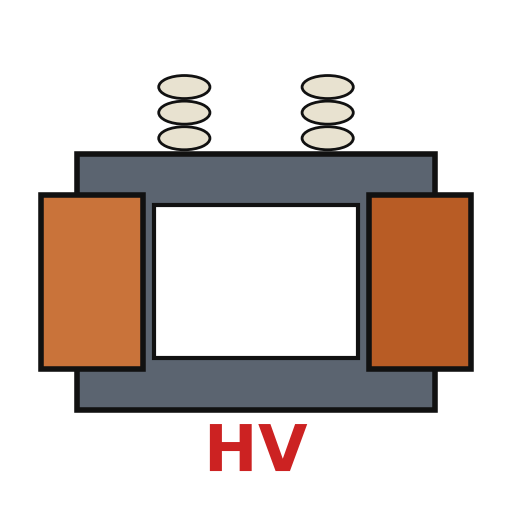
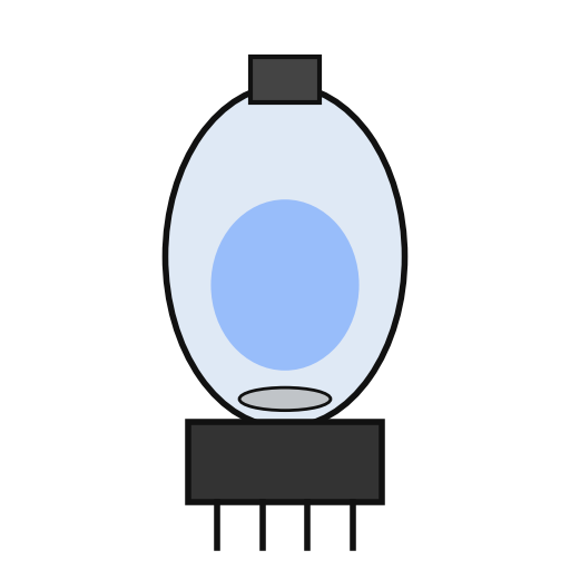
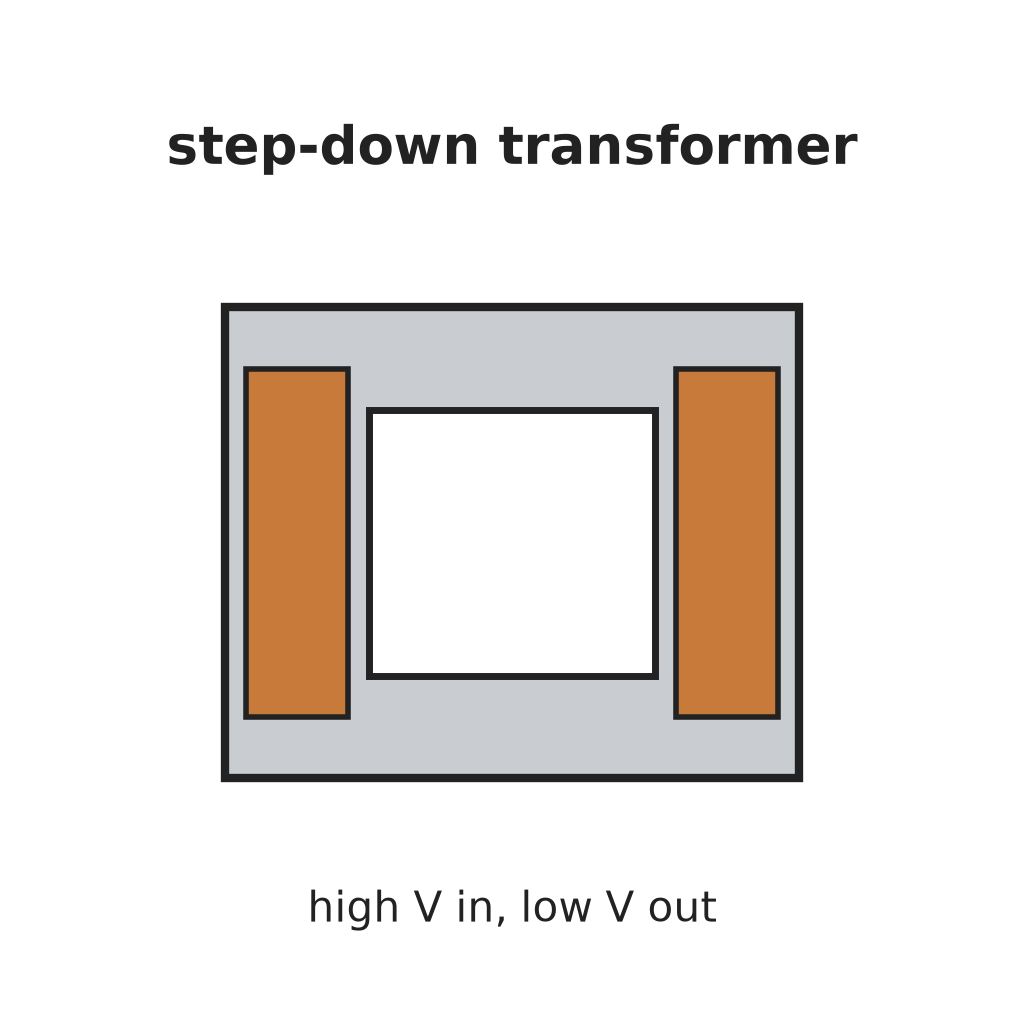
Feed a line switch from the mains through two fuses, with a pilot lamp. Wire a high-voltage transformer with two primaries, which a high-low switch puts in series or in parallel. Run its centre-tapped secondary to two mercury-vapour rectifier tubes, "or the like", with their own filament transformer, so they charge the energy-storage capacitor. A charging on-off switch with a red lamp switches the high-voltage side. A meter with multiplier resistors across the capacitor shows its voltage. Ours: toggle switches, neon lamps, a moving-coil meter. Not given: any voltage or value.
このステップの材料:
 高電圧変圧器1 high-voltage transformer
 水銀蒸気整流管2 rectifier tubes
 降圧トランス1 filament transformer
 エネルギー蓄積コンデンサ1 storage capacitor
 可動コイル形パネルメーター1 voltage meter
 不明な抵抗器2 meter multipliers
 トグルスイッチ3 line, charging and high-low switches
 ヒューズ2 fuses
 ネオン表示ランプ2 pilot and red lamps
必要な工具:
 はんだごて
 ワイヤーストリッパー
2
2
Add the delay and the bleeder
Add the delay and the bleeder
Put a thermal time-delay relay before the charging switch: about thirty seconds after switch-on it energises a control relay, which feeds the charging switch and holds itself on. A third contact of the control relay lifts a bleeder resistor off the capacitor while the charger runs. When the charger is shut down the relay drops out and the bleeder drains the dangerous high-voltage charge from the capacitor.
このステップの材料:
 タイマーリレー(限時継電器)1 thermal delay relay
 リレー1 control relay, three contact sets不明な抵抗器1 bleeder resistor
必要な工具:
はんだごてワイヤーストリッパー3
3
Fit the ignitron firing circuit
Fit the ignitron firing circuit
Put an ignitron in the discharge path of the storage capacitor, as its switch. The meter's multiplier resistors also form a divider that charges a small firing capacitor. Pressing the push button discharges the firing capacitor through a small limiting resistor into the ignitron's igniter, and the ignitron conducts. Not given: the firing capacitor's type and value.
このステップの材料:
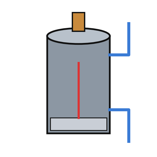 イグナイトロン1 discharge switch
 不明な材料1 firing capacitor不明な抵抗器1 limiting resistor
 押しボタン1 charge button
必要な工具:
はんだごてワイヤーストリッパー4
4
Build the wire-wound fixture
Build the wire-wound fixture
Weld a hollow cylindrical shell onto a base plate on levelling legs, both of magnetic material, to make a pot. Cut slots through the shell and the base plate so they cannot act as a shorted single-turn winding. Set the coil inside the shell in potting compound, with ring-shaped end pieces and a hollow cylindrical core in it. Hinge a square magnetic cover on a post beside the shell, held by a collar and set screw, with a handle. An L-shaped plate on the cover closes a switch in the igniter circuit only when the cover is shut. Wire the coil between the storage capacitor and the ignitron anode. Ours: mild steel, enamelled copper wire, casting epoxy. Not given: sizes, turns.
このステップの材料:
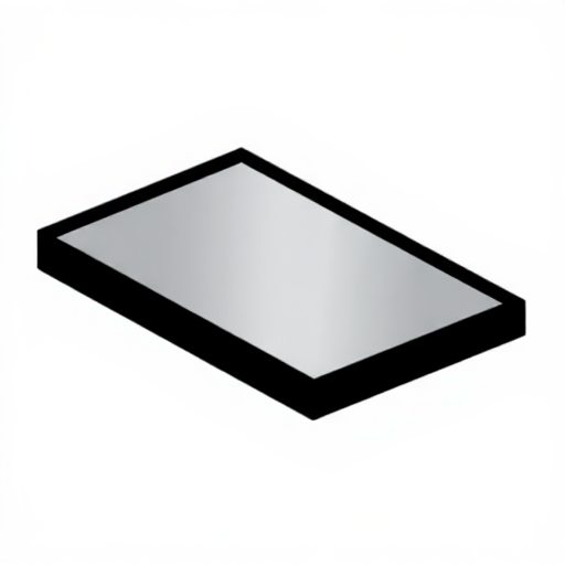 軟鋼板1 base plate and cover
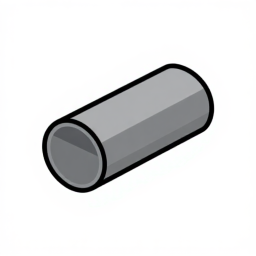 軟鋼の丸管1 shell
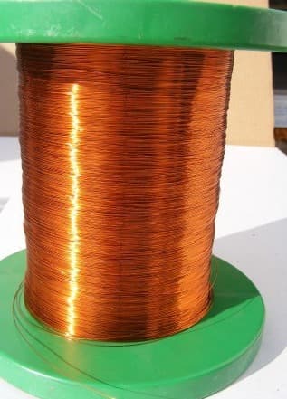
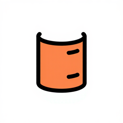 エナメル被覆銅線1 coil
 黒の注型エポキシ1 potting compound
 不明な金属1 end pieces, core, post, legs
 マイクロスイッチ(レバー式)1 lid interlock switch
必要な工具:
 アーク溶接機
 ボール盤
 ドライバーセット
 不明な寸法
5
5
Charge a magnet
Charge a magnet
Put the magnet inside the core. Fill most of the air gap between it and the base plate and cover with soft iron, but leave a small gap near the cover, or the cover will be hard to swing open afterwards. Lay insulating material about 1/16 inch thick on top of the magnet. Close the cover, which arms the igniter switch, charge the capacitor, and press the button: one pulse magnetises it. Ours: wrought iron for the soft iron.
必要な工具:
 錬鉄の棒
 不明な絶縁材料
材料
20- 1 high-voltage transformerプレースホルダー
- 2 rectifier tubesプレースホルダー
- 1 filament transformerプレースホルダー
- 1 storage capacitorプレースホルダー
- 1 voltage meterプレースホルダー
- 1 limiting resistorプレースホルダー
- プレースホルダー
- 2 fusesプレースホルダー
- 2 pilot and red lampsプレースホルダー
- 1 thermal delay relayプレースホルダー
- 1 control relay, three contact setsプレースホルダー
- 1 discharge switchプレースホルダー
- 1 firing capacitorプレースホルダー
- プレースホルダー
- 1 base plate and coverプレースホルダー
- 1 shellプレースホルダー
- 1 coilプレースホルダー
- 1 potting compoundプレースホルダー
- 1 end pieces, core, post, legsプレースホルダー
- 1 lid interlock switchプレースホルダー
接続ブループリントの材料


この設計図で作るもの
CC0 パブリックドメイン
このブループリントはCC0で公開されています。許可を求めずに、自由にコピー、修正、配布、あらゆる目的で使用できます。
メイカーを応援するには、ブループリント経由で製品を購入してください。メイカーには メイカーコミッション がベンダーにより設定されています。または、このブループリントの新しいイテレーションを作成し、自分のブループリントにコネクションとして含めて収益を共有できます。