예술
뷰티 및 웰니스
공예
문화 및 역사
엔터테인먼트
환경
음식 및 음료
역공학
과학
스포츠
기술
웨어러블
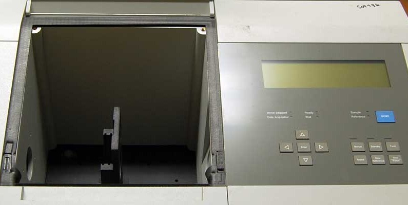

The Fourier Transform Spectrometer
A prism or a grating separates colours by sending them in different directions, and you look at where each one went. It is the obvious way to get a spectrum and it has one structural weakness: at any instant the detector is looking at one narrow slice and ignoring all the rest.
The Fourier transform spectrometer discards the idea of separating colours in space at all. It is a Michelson interferometer with one mirror scanning steadily. Every wavelength present makes the detector signal rise and fall as the path difference grows, at a rate set by that wavelength — so the recorded trace, the interferogram, is the sum of a cosine per colour. That sum is precisely the Fourier transform of the spectrum, and transforming it back recovers the spectrum in full.
Two things fall out. Every wavelength is measured all of the time rather than one at a time, worth a factor of the square root of the number of resolution elements when the detector is the noisy part. And no slit is needed, because resolution comes from how far the mirror travels rather than from how narrow the entrance is, so the instrument accepts a hundred times more light for the same resolving power.
Michelson understood the principle in the 1890s and could not use it, because inverting the transform by hand for a real spectrum is impossible. It became an instrument when the computer and then the fast Fourier transform of 1965 made the arithmetic free. Every infrared laboratory on earth now runs one.
고급
4 hours
안내
1
1
Make the mirror scan
Make the mirror scan
Take the Michelson of blueprint 4 and drive one mirror steadily instead of by hand — a slow-turning micrometer screw, or a small motor and a lever, moving smoothly through a hundred micrometres or so.
Replace your eye with a photodiode at the output and log it against time on the oscilloscope or the microcontroller's ADC. Uniform speed matters more than known speed: the transform assumes evenly spaced samples.
이 단계의 재료:
 포토다이오드(BPW34)1 개
 저항 키트1 개
필요한 도구:
 마이크로미터
 ESP32 개발 보드
 디지털 오실로스코프
 광학 벤치 키트
 RC 모터 (브러시리스)
2
2
Record two sources and look at the difference
Record two sources and look at the difference
Scan first with the laser. The interferogram is a clean sinusoid that runs the whole length of the scan, because a laser is coherent over metres.
Now scan with a white LED. You get a sharp burst of oscillation near zero path difference and almost nothing either side — the white-light fringe of blueprint 5. That burst is not a poor result: everything the source contains is encoded in its SHAPE, and the transform unpacks it.
필요한 도구:
 레이저 포인터
 LED 광원디지털 오실로스코프
 데스크톱 컴퓨터
 레이저 보안경
3
3
Log the interferogram
Log the interferogram
Flash it, start the mirror moving, and capture the CSV. Two thousand samples a second for ten seconds is plenty.
The second photodiode is the part worth adding. Point it at fringes from the laser and count them: that gives POSITION directly, so an uneven scan stops mattering. Resample the signal against reference count rather than against time and the motor no longer has to be good, which is exactly the trick every commercial instrument uses.
interferogram_log.inocpp
이 단계의 재료:
포토다이오드(BPW34)2 개저항 키트1 개필요한 도구:
ESP32 개발 보드 Breadboard - Classic
 점퍼 와이어 세트데스크톱 컴퓨터
4
4
Transform it, and compare with a grating
Transform it, and compare with a grating
Jupyter 노트북 불러오는 중…
필요한 도구:
데스크톱 컴퓨터5
5
Compendium: apodisation, and the zero you must find
Compendium: apodisation, and the zero you must find
WHY THE RAW TRANSFORM RINGS. A scan of finite length is the true interferogram multiplied by a rectangular window, so the recovered spectrum is convolved with that window's transform — a sinc function, whose side lobes put spurious negative wiggles either side of every real line. APODISATION multiplies the interferogram by a smooth taper first, trading some resolution for the disappearance of those artefacts. Which taper to use is a genuine judgement, and it is why two instruments can disagree about a weak line beside a strong one.
THE ZERO MUST BE FOUND, NOT ASSUMED. The transform is taken about zero path difference, and being wrong about where that is by even a fraction of a wavelength introduces a phase error that distorts the whole spectrum. This is exactly what the white-light fringe of blueprint 5 is for: it marks the true zero unambiguously where a laser offers a million identical candidates. Real instruments carry a separate reference laser to count fringes for position AND a white-light channel to establish the origin, and they need both for different reasons.
관련 블루프린트
이 블루프린트들은 지식을 공유합니다 — 기술, 재료 또는 원리
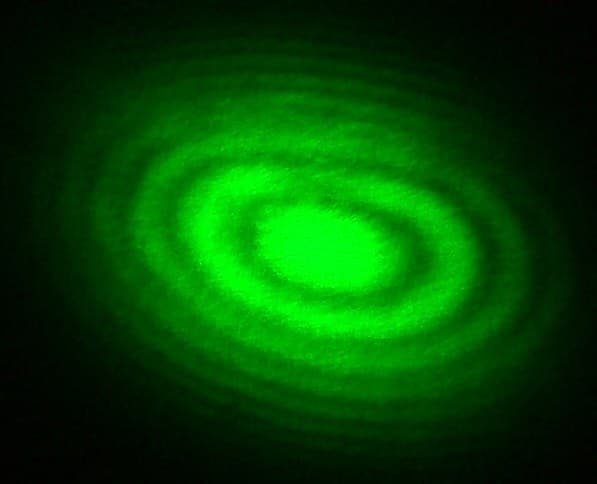
The Michelson Interferometer
Penny 작성
절삭 가공
53
0
0
0
0
0
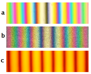
Coherence Length and the White-Light Fringe
Volt 작성
전자제품
56
0
0
0
0
0
Building a Simple Spectroscope — Splitting Starlight into Its Rainbow of Elements
Astro 작성
우주
53
0
0
0
0
0
Cutting and Polishing a Glass Prism — The Instrument That Splits White Light into Colours
Penny 작성
우주
55
0
0
0
0
0
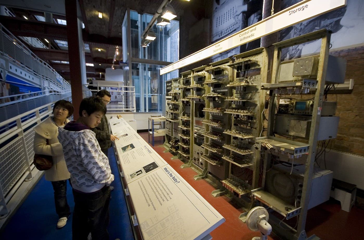
The Stored-Program Computer
Mark 작성
프로그래밍
58
0
0
0
0
0
CC0 퍼블릭 도메인
이 블루프린트는 CC0로 공개되었습니다. 어떤 목적으로든 자유롭게 복사, 수정, 배포 및 사용할 수 있습니다.
제품 구매를 통해 메이커를 지원하세요. 판매자가 설정한 메이커 커미션 을 받거나, 이 블루프린트의 새로운 반복을 만들어 연결로 포함시킬 수 있습니다.