ARTE
BELLEZA Y BIENESTAR
ARTESANÍA
CULTURA E HISTORIA
ENTRETENIMIENTO
MEDIO AMBIENTE
COMIDA Y BEBIDAS
INGENIERÍA INVERSA
CIENCIAS
DEPORTES
TECNOLOGÍA
TECNOLOGÍA VESTIBLE
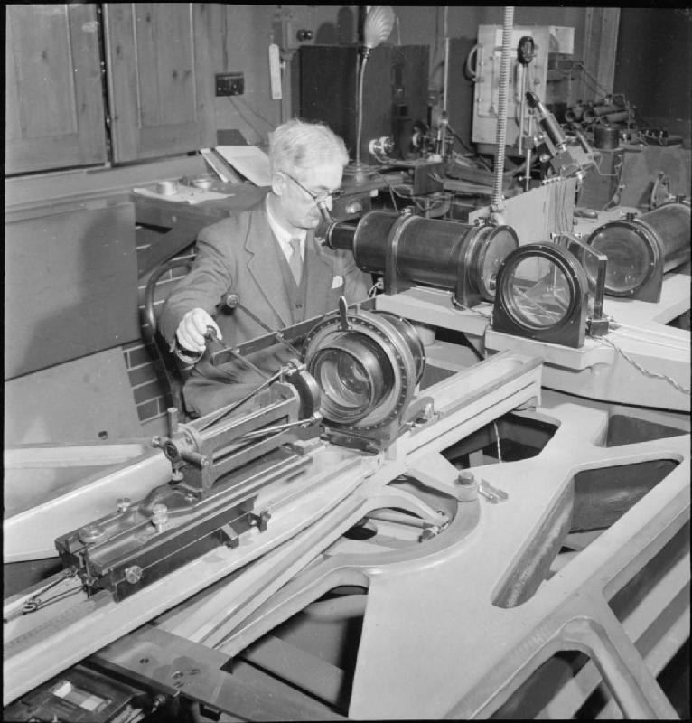

The Twyman-Green Interferometer
Frank Twyman and A. Green patented one change to the Michelson in 1916 and turned a physics instrument into a production tool. Illuminate it with a COLLIMATED beam — a plane wave rather than a point source — and put the optic you want to test in one arm, with a mirror behind it to send the light back through.
A perfect optic returns the plane wave unchanged and the fringes are dead straight. A real one returns a wavefront with its own errors printed into it, and the fringes bend by exactly that much. The pattern is a contour map of the optic's error, in steps of half a wavelength, and because the light passes through twice the error is doubled and therefore easier to see.
The Fizeau wedge of blueprint 3 already maps a surface, and does it more cheaply. What it cannot do is test anything that is not a flat you can lay a reference against — a cemented doublet, a prism, a whole telescope. Moving the optic into an ARM of an interferometer removes that constraint completely, at the cost of a collimator and about two orders of magnitude in money.
It also produces the one number an optical shop can put on a certificate: peak-to-valley wavefront error, against the quarter-wave criterion below which an optic is as good as its aperture allows and polishing further buys nothing at all.
Avanzado
4 hours
Instrucciones
1
1
Collimate, then insert the optic
Collimate, then insert the optic
Start from the Michelson of blueprint 4. Expand the laser through a short-focus lens and re-collimate it with a longer one, so the beam leaves as a wide plane wave — check by confirming the spot does not change size across three metres.
Put the lens under test in one arm with a front-surface mirror behind it, positioned so the light comes back on itself. Re-find the fringes.
Materiales para este paso:
 Juego de lentes planoconvexas1 pieza
 Espejo de primera superficie1 pieza
 Cubo divisor de haz1 pieza
Herramientas necesarias:
 Kit de banco óptico
 Puntero láser
 Gafas de protección láser
 Regla
Regla2
2
Null the tilt and read the bow
Null the tilt and read the bow
Adjust the reference mirror until the fringes are as wide and as straight as you can make them. That removes tilt and defocus, which are alignment rather than optic error.
Photograph the pattern. As in blueprint 3, measure the fringe spacing and the greatest departure of a fringe from straight, and divide. Test the same lens turned through ninety degrees: astigmatism shows up as a bow that rotates with the optic, and mounting strain as one that does not.
Herramientas necesarias:
 Ordenador de sobremesaRegla
3
3
Wavefront error, Rayleigh, Strehl
Wavefront error, Rayleigh, Strehl
Cargando el cuaderno de Jupyter…
Herramientas necesarias:
Ordenador de sobremesa4
4
Compendium: what the fringes cannot tell you
Compendium: what the fringes cannot tell you
TILT AND DEFOCUS ARE NOT ERRORS. Straight evenly spaced fringes mean tilt; circular ones mean the return mirror is at the wrong distance. Both are how you SET THE THING UP and both are removed before anything is measured, which is why a Twyman-Green result is always quoted after subtracting them. Confusing an alignment fringe pattern with an optic's error is the classic beginner's result, and it always reads far worse than the optic deserves.
THE SIGN AMBIGUITY, AND HOW THE MODERN INSTRUMENT ESCAPES IT. A single fringe pattern cannot tell a bump from a dip: both bend the fringes the same way. Traditionally you resolved it by introducing a known tilt and watching which way the bow moved. A modern phase-shifting interferometer instead steps the reference mirror through a fraction of a wavelength with a piezo, captures several frames, and computes the phase at every pixel unambiguously — which is how the same 1916 layout now delivers a full surface map to a hundredth of a wave rather than a photograph to be interpreted by eye.
Materiales
3- Marcador de posición
- 1 piezaMarcador de posición
- 1 piezaMarcador de posición
Herramientas requeridas
5- Marcador de posición
- Marcador de posición
- Marcador de posición
- Marcador de posición
- Marcador de posición
Blueprints relacionados
Estos blueprints comparten conocimiento — técnicas, materiales o principios
The Michelson Interferometer
por Penny
Fabricación Sustractiva
55
0
0
0
0
0
The Fizeau Wedge and the Optical Flat
por Emma
Fabricación Sustractiva
56
0
0
0
0
0
Foucault Knife-Edge Test
por Astro
CIENCIAS
52
0
0
0
0
0
Achromatic Lens
por Penny
Física
46
0
0
0
0
0
Building a Newtonian Reflecting Telescope — Mirrors Instead of Lenses
por Astro
Carpintería
98
1
0
0
2
0
CC0 Dominio público
Este Blueprint se publica bajo CC0. Eres libre de copiar, modificar, distribuir y usar este trabajo para cualquier propósito, sin pedir permiso.
Apoya al Maker comprando productos a través de su Blueprint, donde gana una Comisión del Maker establecida por los vendedores, o crea una nueva iteración de este Blueprint e inclúyela como conexión en tu propio Blueprint para compartir ingresos.