

Screw Propeller
Early steamships were driven by paddle wheels hung on their sides. Paddles work, but they lift half their blades uselessly into the air on every turn, they slap and stall in a rough sea, they roll clear of the water when the ship heels, and on a warship they are a huge target sitting right where the guns should be.
The answer was to put the drive under the water: a screw that pulls the ship forward the way a woodscrew pulls itself into a plank. Fully submerged, it works the same in calm and in swell, and it hides below the waterline.
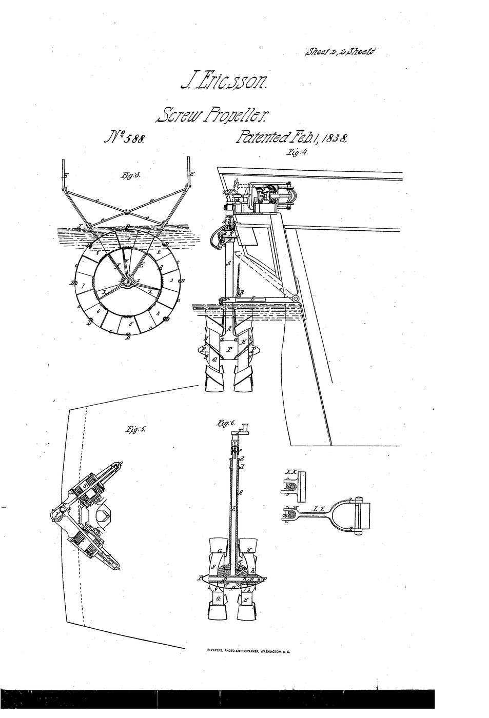
Ericsson's patent claims a particular form of it — TWO metallic hoops carrying spiral plates, turning in opposite directions at different speeds, and running entirely under water. The counter-rotation cancels the swirl one screw alone leaves behind, so more of the engine's work goes into pushing the ship and less into stirring the sea.
US Patent 588, granted 1 February 1838 to John Ericsson, of London, England. The drawing sheet is captioned "Screw Propeller"; catalogue records for this early patent give the title as "Steam".
Ericsson did not invent the screw propeller, and this blueprint does not claim he did — see the last step.
Ìlànà
Read the claim before you build
Read the claim before you build
Ericsson claims spiral plates on hoops, two of them turning opposite ways at different speeds, and wholly submerged. Write those three points down — you will test each one.
Cut a disc and mark four blades
Cut a disc and mark four blades
Cut a 60 mm disc from thin aluminium sheet. Mark four equal quarters from the centre — these become the blades.
Àwọn ohun èlò fún ìgbésẹ̀ yìí:
 Àwo aluminiomu1 ewé
Àwọn irinṣẹ́ tí a nílò:
 Ìkẹ́rẹ́ aṣọ
 Ẹ̀rọ Ìwọ̀n Igun
Twist each blade to 30°
Twist each blade to 30°
Cut in along each mark to the centre, then twist all four blades the same way to about 30° off flat. Measure the angle with the protractor — equal on all four.
Àwọn irinṣẹ́ tí a nílò:
Ẹ̀rọ Ìwọ̀n IgunMount the screw on a shaft
Mount the screw on a shaft
Push a dowel through the disc centre and fix it. The blades must sit square to the shaft so the screw runs true.
Àwọn ohun èlò fún ìgbésẹ̀ yìí:
 Òpó Igi Dòwẹ̀lì1 ẹyọ
Àwọn irinṣẹ́ tí a nílò:
 Ìbọn ìlẹ̀mọ́ gbígbóná
Build a balsa hull
Build a balsa hull
Cut a simple 200 mm hull from balsa. Notch the stern so the shaft can run through it and the screw sits behind and below the hull.
Àwọn ohun èlò fún ìgbésẹ̀ yìí:
 Ìwé Igi Balsa1 ewé
Àwọn irinṣẹ́ tí a nílò:
 Ọ̀bẹ Iṣẹ́ Ọwọ́
Fit a rubber-band motor
Fit a rubber-band motor
Hook a rubber band from the shaft to a peg at the bow. Winding the screw twists the band; letting go unwinds it and spins the screw.
Àwọn ohun èlò fún ìgbésẹ̀ yìí:
 Okùn rọ́bà1 àkópọ̀
Run it fully submerged
Run it fully submerged
Float the boat in a basin with the screw completely under water. Wind 30 turns, release, and time the run over 500 mm.
Àwọn ohun èlò fún ìgbésẹ̀ yìí:
 Àwokòtò ìkójọ1 ẹyọ
Àwọn irinṣẹ́ tí a nílò:
 Aago Ìdúró
 Okùn Ìdíwọ̀n
Now lift it half out — Ericsson's third point
Now lift it half out — Ericsson's third point
Pack the stern up so the screw runs half in air. Same 30 turns. It slows and throws spray: a half-submerged screw wastes its work. That is why the claim says wholly submerged.
Àwọn irinṣẹ́ tí a nílò:
Aago ÌdúróChange the pitch and re-run
Change the pitch and re-run
Make a second screw twisted to about 15°. Run both. Note which is quicker — too flat barely bites, too steep stalls the band.
Àwọn ohun èlò fún ìgbésẹ̀ yìí:
Àwo aluminiomu1 ewéÀwọn irinṣẹ́ tí a nílò:
Ẹ̀rọ Ìwọ̀n IgunAago ÌdúróSee the swirl a single screw leaves
See the swirl a single screw leaves
Sprinkle a pinch of pepper on the water behind the running screw. The wake rotates — that spin is energy going round instead of backward.
Feel the torque reaction
Feel the torque reaction
Hold the hull loosely and release the band. The hull tries to roll the opposite way to the screw. One screw twists the ship as well as pushing it.
Why Ericsson used two
Why Ericsson used two
Turn a second screw by hand the opposite way just behind the first. Its blades meet the swirling wake head-on. Two counter-rotating screws cancel both the swirl and the roll — Ericsson's central claim.
Compare with a paddle
Compare with a paddle
Tape a flat card paddle to the shaft instead and run it half-submerged. It slaps, sprays and pushes the bow off line — the problem the screw was built to solve.
Àwọn ohun èlò fún ìgbésẹ̀ yìí:
 Àwọn Pẹlẹbẹ Káàdíbóòdù Onílọ́nà1 ewé
 Tépù ìbòmọ́lẹ̀1 ìyípo
History & Context — who really invented the screw propeller
History & Context — who really invented the screw propeller
The patent. US 588, granted 1 February 1838 to John Ericsson, of London, England. Ericsson claims spiral plates carried on metallic hoops, a pair of them running in opposite directions at different velocities, wholly immersed, giving greater propelling force from a smaller propeller than earlier designs.
📌 The title depends where you look, and that is worth knowing. Google Patents records this patent as "Steam" — an artefact of how these very early US patents were catalogued under broad headings. The drawing sheet itself is headed "J. Ericsson — Screw Propeller — No 588 — Patented Feb 1, 1838". When a catalogue record and the document disagree, the document wins. The specification pages are the same story: they describe hoops, spiral plates, contrary directions and unequal velocities, and state the invention is useful "for ships of war or merchant vessels".
Ericsson did not invent the screw propeller, and it matters to say so. The idea of a helix driving a vessel is ancient — the Archimedes screw is its ancestor, and by the 1830s several people were converging on it. Francis Pettit Smith patented a screw propeller in Britain in 1836, weeks before Ericsson's own British patent of the same year. Ericsson's document claims a particular form: the hooped, contra-rotating, fully submerged arrangement. Read the claims, not the legend — a patent tells you what one person claimed, not who was first.
What the counter-rotation is for. A single screw leaves a spinning wake (step 10) and twists the hull the other way (step 11). Both are wasted engine power. A second screw turning the opposite way straightens the wake and cancels the reaction torque. Contra-rotating propellers are still used today on torpedoes and some ships for exactly this reason — though most vessels settle for one screw, because two shafts running through one stern is expensive and awkward to maintain.
What happened next. Ericsson demonstrated a screw-driven launch, the Francis B. Ogden, on the Thames in 1837; the Admiralty was famously unimpressed. He moved to the United States, and his screw drive went into the USS Princeton (1843), the first screw-propelled warship, with the engines below the waterline where shot could not reach them — the naval argument that finally killed the paddle wheel. Ericsson was Swedish by birth, from Värmland, and is better remembered by most people for a later ship entirely: the ironclad Monitor of 1862.
Where it sits. Every propeller-driven ship afloat is doing what your balsa hull did — biting a fixed pitch of water per turn and shoving it astern. The engineering since 1838 has been about blade shape, cavitation and efficiency, not about the principle. The principle you just measured with a protractor and a rubber band.
Àwọn ohun-èlò
7- 1 ewéÀyè
- 1 ẹyọÀyè
- 1 ewéÀyè
- 1 àkópọ̀Àyè
- 1 ẹyọÀyè
- Àyè
- 1 ìyípoÀyè
Àwọn irinṣẹ́ tó nílò
6- Àyè
- Àyè
- 1 vendor sell this, none ship to you yetÀyè
Àwọn Ohun Èlò Ìtọ́nisọ́nà Tí A So Pọ̀

Blueprint tó jọra
Àwọn blueprint wọ̀nyí pín ìmọ̀ — ọ̀nà, ohun-èlò tàbí ìlànà


CC0 Àgbègbè Gbogbogbò
Blueprint yìí ti jáde lábẹ́ CC0. O lè ṣe àdàkọ, yí padà, pín, àti lò láìsí ìyọ̀ǹda.
Ṣàtìlẹ́yìn Olùṣẹ́dá nípa rírà àwọn ọjà nipasẹ̀ Blueprint wọn Ẹ̀san Olùṣẹ́dá tí àwọn Olùtajà gbé kalẹ̀, tàbí ṣẹ̀dá àtúnṣe tuntun ti Blueprint yìí kí o sì fi sínú Blueprint rẹ gẹ́gẹ́ bí ìsopọ̀ láti pín owó-wíwọlé.