Współpraca
SZTUKA
Piękno i dobre samopoczucie
RZEMIOSŁO
KULTURA I HISTORIA
ROZRYWKA
ŚRODOWISKO
JEDZENIE I NAPOJE
INŻYNIERIA ODWROTNA
NAUKI
LEKKOATLETYKA
TECHNOLOGIA
URZĄDZENIA DO NOSZENIA
Friction Plunger Churn: Cream Pumped Through Openings You Close a Little More as It Thickens
Buttercup

Autor

Buttercup

10. listopad 2026IE
6
0
0
0
0

Friction Plunger Churn: Cream Pumped Through Openings You Close a Little More as It Thickens

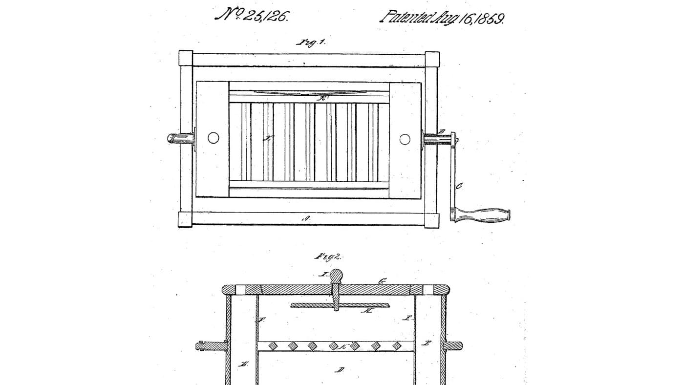
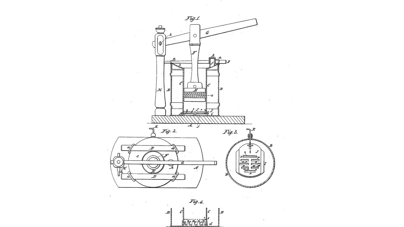
John J. Lehaye of Reading, Pennsylvania, received US 25,162, dated 16 August 1859, for a churn that works by friction. A hollow cylinder stands inside the cream vessel on two slotted plates. A packed plunger, worked by a long lever, draws the cream from the vessel into the cylinder through the slots and drives it back. A screw rod through a stuffing box in the vessel's side slides the upper plate, so the openings can be narrowed as the churning goes on. Lehaye gives no sizes; every size here is ours.
Średniozaawansowany
About 2 days, plus printing

Instrukcje

1

How hard the cream is rubbed through the openings

Wczytywanie notatnika Jupyter…
2

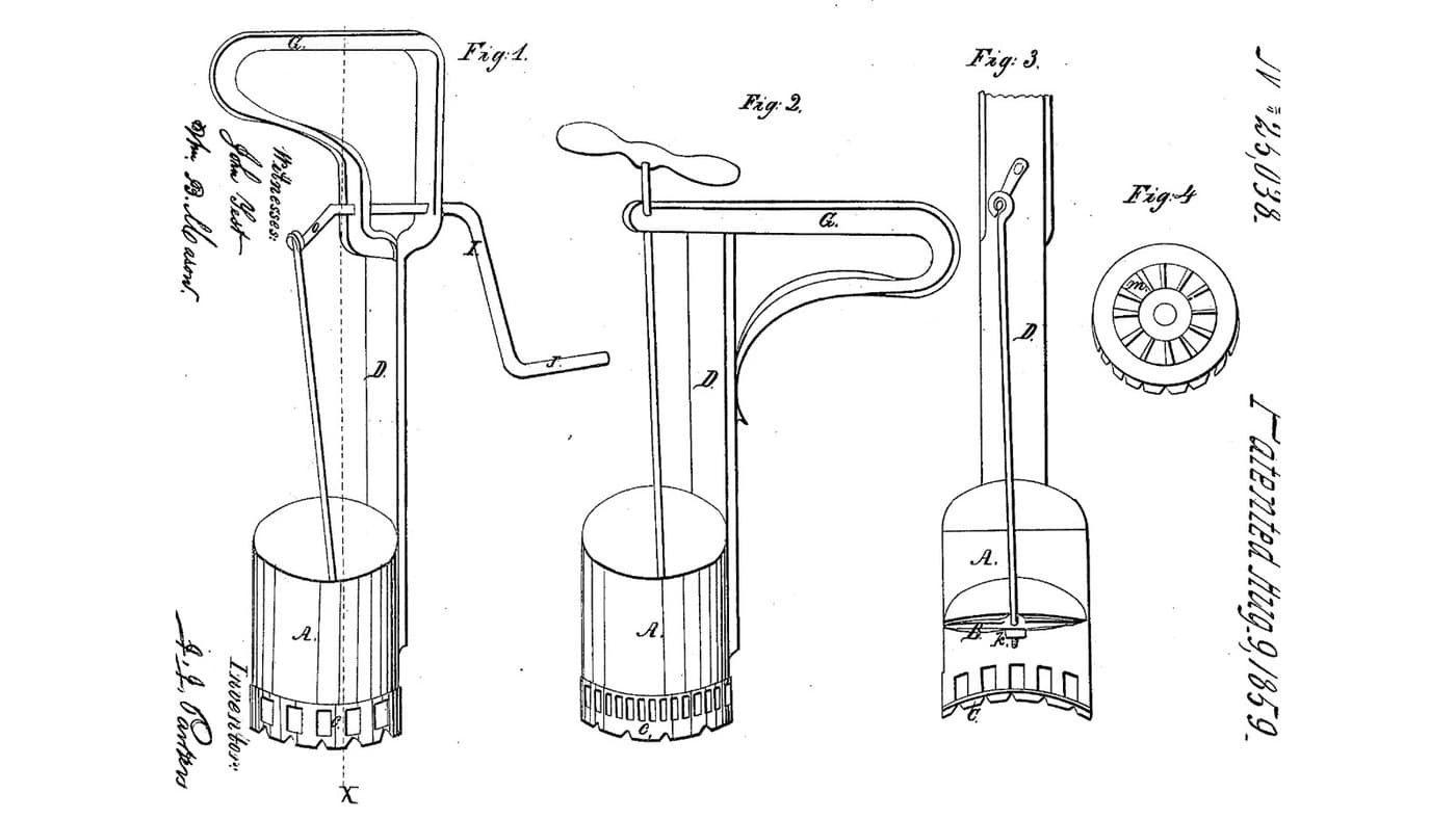
A piston that draws through a grate, the week before

Parker's beater pumped eggs through fixed openings. Lehaye's openings close a little more as the cream thickens.
3

Read US 25,162

"By causing the cream to pass and repass through contracted openings, and with considerable force, the friction of the cream against the edges of the openings has the effect of rapidly separating the butter from the whey at the same time the constant change in the course of the cream agitates the latter as effectually as the ordinary dashers."
4

Print the plate I

The 200 mm lower plate on four 20 mm legs i, with six 8 x 50 mm openings 18 mm apart and two guide flanges for plate J. Print it legs up. PETG, 0.2 mm layers, 30 % infill, 4 walls.
Plik projektowySTLCC0 - Free
5

Print the plate J

The 116 x 64 mm sliding plate with six openings matching plate I's and a boss at one end for rod K's nut. PETG, 0.2 mm layers, 30 % infill, 4 walls.
Plik projektowySTLCC0 - Free
6

Print the cylinder rings

One 86.5 mm ring of the cylinder C, 160 mm across with a 3 mm wall and a spigot on top. Print three. PETG, 0.2 mm layers, 30 % infill, 4 walls.
Plik projektowySTLCC0 - Free
7

Print the bottom cylinder ring

The bottom ring, with an 18 mm notch in its lower edge for rod K. PETG, 0.2 mm layers, 30 % infill, 4 walls.
Plik projektowySTLCC0 - Free
8

Print the plunger's upper plate

A 152 mm plate with a hub bored 6.4 mm across for rod F's pin. PETG, 0.2 mm layers, 30 % infill, 4 walls.
Plik projektowySTLCC0 - Free
9

Print the plunger's lower plate

The plain 152 mm plate with a 6.4 mm hole in the middle. PETG, 0.2 mm layers, 30 % infill, 4 walls.
Plik projektowySTLCC0 - Free
10

Print the stuffing box's inner half

The flanged boss that sits inside the bucket, with an O-ring groove in its face and two 4.4 mm screw holes. PETG, 0.2 mm layers, 30 % infill, 4 walls.
Plik projektowySTLCC0 - Free
11

Print the stuffing box's outer half

The flanged boss outside the bucket, with a groove in its bore for a 6 mm O-ring round rod K. PETG, 0.2 mm layers, 30 % infill, 4 walls.
Plik projektowySTLCC0 - Free
12

Print the vent tube

The 20 mm tube through the flange that lets the gases out. PETG, 0.2 mm layers, 30 % infill, 4 walls.
Plik projektowySTLCC0 - Free
13

Print the vent's cover k

The push-on cover for the vent tube. PETG, 0.2 mm layers, 30 % infill, 4 walls.
Plik projektowySTLCC0 - Free
14

Base A and column H

Cut an 18 mm plywood base 750 x 400 mm. Stand a hardwood column 70 x 70 mm, 643 mm tall, on it 290 mm from where the bucket's middle will be, glued and screwed from under the base. Saw a slot 24 mm wide and 100 mm deep in its top and bore it 12.4 mm across 40 mm below the top for the pin h.

Materiały do tego kroku:

Płyta sklejkowaPłyta sklejkowa1 sztuka
Deska z drewna liściastegoDeska z drewna liściastego1 sztuka
Klej do drewnaKlej do drewna1 sztuka
Wkręty do drewnaWkręty do drewna6 sztuk

Potrzebne narzędzia:

WyrzynarkaWyrzynarka
Piła ręcznaPiła ręczna
DłutaDłuta
Wiertarko-wkrętarka akumulatorowaWiertarko-wkrętarka akumulatorowa
Zestaw wierteł łopatkowychZestaw wierteł łopatkowych
Zestaw wiertełZestaw wierteł
Kątownik stolarskiKątownik stolarski
Miara zwijanaMiara zwijana
15

Bucket B and the stuffing box

Screw the bucket's floor to the base. Drill a 20.4 mm hole in its side 30 mm above the floor, facing away from the column, and two 4.4 mm holes 19 mm either side of it. Lay a 30 x 2 mm O-ring in the inner half's groove, fit the halves inside and outside the wall and draw them together with two stainless M4 screws and lock nuts. Fill the bucket with water to check the box does not leak, then empty it.

Materiały do tego kroku:

Wiadro 20-litroweWiadro 20-litrowe1 sztuka
Wkręty do drewnaWkręty do drewna4 sztuk
O-ringO-ring2 sztuk
Śruby maszynoweŚruby maszynowe2 sztuk
Nakrętka samohamowna z wkładką nylonowąNakrętka samohamowna z wkładką nylonową2 sztuk
Filament PETGFilament PETG1 sztuka

Potrzebne narzędzia:
Drukarka 3D z filamentem (FDM)Drukarka 3D z filamentem (FDM)
Wiertarko-wkrętarka akumulatorowaWiertarko-wkrętarka akumulatorowa
Zestaw wierteł łopatkowychZestaw wierteł łopatkowych
Zestaw wiertełZestaw wierteł
Zestaw wkrętakówZestaw wkrętaków
Klucz nastawnyKlucz nastawny
WodaWoda
16

Plates I and J, and rod K

Press an M6 nut into plate J's boss. Lay J on plate I between its flanges and stand I on its legs in the middle of the bucket's floor. Cut 170 mm of M6 stainless threaded rod, bend 40 mm of one end to an L for a handle, push the straight end in through the stuffing box with a 6 mm O-ring in its bore and screw it into J's nut. Turn K both ways: J slides until its openings line up with I's, and closes them after 8 mm.

Materiały do tego kroku:

Nakrętka sześciokątnaNakrętka sześciokątna1 sztuka
Pręt gwintowanyPręt gwintowany1 sztuka
O-ringO-ring1 sztuka

Potrzebne narzędzia:

Piła do metaluPiła do metalu
Imadło warsztatoweImadło warsztatowe
Klucz nastawnyKlucz nastawny
17

Cylinder C, flange c, staples and wedges

Stack the four rings on plate I, the notched one at the bottom over rod K. Cut the flange from 12 mm plywood, a ring 304 mm across with a 154 mm hole, and bore a 16 mm hole 125 mm from its middle for the vent. Set it on the bucket's rim over the cylinder's top. Fit four stainless U-bolts through the bucket wall just under the rim, two each side, and drive two tapered hardwood wedges, 340 x 30 mm and 16 mm at their thick end, through them over the flange so it presses the cylinder down on the plates. Push the vent tube into its hole and its cover on top.

Materiały do tego kroku:

Płyta sklejkowaPłyta sklejkowa1 sztuka
Strzemię w kształcie litery UStrzemię w kształcie litery U4 sztuk
Deska z drewna liściastegoDeska z drewna liściastego1 sztuka
Filament PETGFilament PETG1 sztuka

Potrzebne narzędzia:

WyrzynarkaWyrzynarka
Zestaw wierteł łopatkowychZestaw wierteł łopatkowych
Wiertarko-wkrętarka akumulatorowaWiertarko-wkrętarka akumulatorowa
Zestaw wiertełZestaw wierteł
Piła ręcznaPiła ręczna
Klucz nastawnyKlucz nastawny
18

Plunger E, rod F and arm G

Cut two 153.9 mm discs of 3 mm food-grade silicone sheet and bolt them between the plunger plates through the middle, hub up; the silicone's edge is the packing e and should slide in the cylinder with a light drag. Saw a slot in each end of a 22 mm hardwood dowel 470 mm long between pin centres and pin its lower end to the plunger's hub with a 6 mm stainless bolt. Make the arm G from hardwood 40 x 22 mm, 930 mm long, bore it 12.4 mm 30 mm from one end for the pin h and 6.4 mm 290 mm from that for rod F, then bolt it into the column's slot with a 12 mm bolt and pin rod F to it.

Materiały do tego kroku:

Płyta z kauczuku silikonowegoPłyta z kauczuku silikonowego1 sztuka
Zestaw śrub sześciokątnychZestaw śrub sześciokątnych4 sztuk
Nakrętka samohamowna z wkładką nylonowąNakrętka samohamowna z wkładką nylonową4 sztuk

Podkładka płaskaPodkładka płaska4 sztuk
Kołki z twardego drewnaKołki z twardego drewna1 sztuka
Deska z drewna liściastegoDeska z drewna liściastego1 sztuka

Potrzebne narzędzia:

NożyczkiNożyczki
Piła ręcznaPiła ręczna
Wiertarko-wkrętarka akumulatorowaWiertarko-wkrętarka akumulatorowa
Zestaw wiertełZestaw wierteł
Klucz nastawnyKlucz nastawny
Miara zwijanaMiara zwijana
19

The build in 3D

FreeCAD model of this build, cut open: the bucket on its base, the slotted plates I and J with rod K through the stuffing box, the cylinder of four rings under the flange, the wedges and staples, the vent, and the plunger on rod F worked by the arm G from the column H. Checked over the lever's whole travel and with plate J slid fully.
Plik projektowyBLENDCC0 - Free
20

Churn

With plate J slid so all the openings are open, pour about 10 litres of heavy cream at about 15 °C into the bucket, checked with the thermometer. Work the arm about once a second, timing it. As the cream thickens, give rod K a turn now and then to close the openings a little. Lift the vent's cover now and then to let the gas out. When the butter comes, knock the wedges out, lift out the flange, the cylinder and the plunger, pour off the buttermilk, wash the butter in cold water until it runs clear, work in a pinch of salt and weigh it.

Materiały do tego kroku:

Śmietanka kremówkaŚmietanka kremówka10 l
Sól morska gruboziarnistaSól morska gruboziarnista1 sztuka
WodaWoda1 sztuka

Potrzebne narzędzia:

Termometr z sondą pozostawianą w potrawieTermometr z sondą pozostawianą w potrawie
StoperStoper
Cyfrowa waga kuchennaCyfrowa waga kuchenna
Duża misa ze stali nierdzewnejDuża misa ze stali nierdzewnej
21

Troubleshooting

Friction plunger churn troubleshooting.

Flow

Loading...
22

History and honest limits

**John J. Lehaye** of Reading, Pennsylvania, assignor to himself and John Tucker of Philadelphia, US 25,162, 16 August 1859, "Churn". He claimed the vessel B, cylinder C and plunger E in combination with means for enlarging or contracting the openings between the cylinder and the vessel. He gives no sizes, so every size here is ours; the U-bolts are his staples a, the O-ring box his stuffing box, and silicone his packing. His Fig. 4 alternative, projections on the cylinder's foot and on a ring in the vessel's bottom, turned to open or close the gaps, is not built. He also offered the machine as an egg beater and for mixing curds.

Materiały

19

Wymagane narzędzia

19

Pliki projektowe

11

CC0 Domena publiczna

Ten plan jest udostępniany na licencji CC0. Możesz go swobodnie kopiować, modyfikować, rozpowszechniać i wykorzystywać do dowolnych celów, bez konieczności uzyskiwania zgody.

Wesprzyj Makera kupując produkty przez jego plan, za co zarabia Prowizja Makera ustalony przez sprzedawców, lub stwórz nową iterację tego planu i dołącz go jako połączenie w swoim własnym planie, aby dzielić się przychodami.

Dyskusja

(0)

Zaloguj się aby dołączyć do dyskusji

Ładowanie komentarzy...