ART
BEAUTY & WELLNESS
CRAFT
CULTURE & HISTORY
ENTERTAINMENT
ENVIRONMENT
FOOD & DRINKS
REVERSE ENGINEERING
SCIENCES
SPORTS
TECHNOLOGY
WEARABLES


Blanking: The Punch, the Die, and the Gap Between Them
Everything made out of sheet starts with a flat shape cut from a bigger flat shape. Get that first operation wrong and nothing downstream recovers: a blank with a rough edge cracks when you bend it, a blank 0.4 mm oversize will not fit the die, and a badly nested layout throws half the sheet in the bin.
Shearing a sheet is not cutting it. The punch and die push the metal in two opposite directions until it **fractures**, and the whole skill is in making the two cracks meet cleanly. The gap between punch and die — the clearance — is what decides that, and it is a percentage of thickness, not a fixed number.
This rung lays out a nest, cuts it, and then reads the cut edge under magnification to work out what the tooling was doing. That last part is a skill you keep.
Beginner
About 3 hours
Instructions
1
1
Lay the nest out before you touch the metal
Lay the nest out before you touch the metal
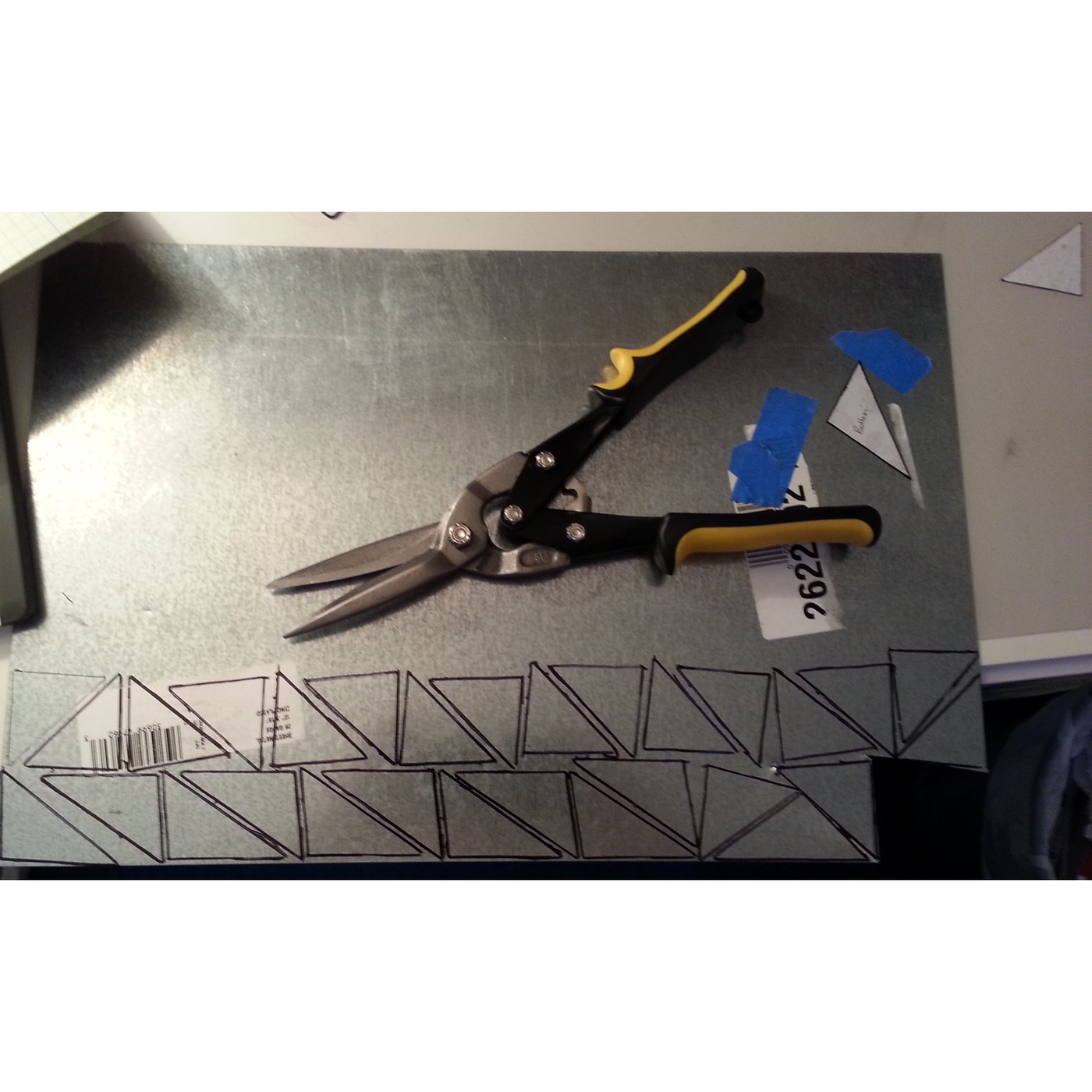
Take a sheet of 20 gauge galvanised steel — about 1 mm — and decide what is coming off it **on paper first**. Draw the sheet to scale on graph paper and draw your parts on it.
Three rules that decide the layout:
1. **Leave a web.** Metal between two parts, and between a part and the sheet edge, needs to be at least one thickness wide, and one and a half is safer. A web thinner than the sheet distorts instead of holding, and the part pulls out of shape.
2. **Turn every second part round.** Two right triangles head to tail occupy one rectangle instead of two. Step 5 works out what that is worth.
3. **Note the grain.** Rolled sheet has a rolling direction, and it bends better across the grain than along it. If a part has a tight bend, orient it so the bend line runs across the grain — rung 2 measures how much difference that makes.
Now transfer it. Wipe the sheet with isopropyl alcohol, brush on a thin coat of layout fluid and let it dry; a scriber line on blue is visible in any light and does not rub off. Set the dividers from the steel rule rather than reading the rule twice, use the combination square for every right angle, and scribe.
Centre-punch every hole position now, while the sheet is flat and supported. Punching a mark in a formed part is a good way to dent it.
Materials for this step:
 Galvanized Steel Sheet 20 Gauge1 piece
 Graph Paper2 pieces
Tools needed:
 Steel Ruler
 Combination Square
 Dividers
 Diamond Scriber
 Center Punch
 Ball Peen Hammer
 Permanent Marker
 Isopropyl Alcohol 99%
 Metal Bluing Solution
2
2
Cut it, and notice which edge came out well
Cut it, and notice which edge came out well
Cut the nest out with aviation snips. They come in three hands and the colours are a standard worth knowing: **yellow cuts straight**, **green curves right**, **red curves left**. Using a straight snip on a tight curve is what makes that crumpled, wavy edge everyone recognises.
Snips shear the same way a die does, with one crucial difference: the blades are not parallel, so the cut happens at a moving point rather than all at once. That is why they need so little force. Watch the offcut curl away as you go — that curl is the waste side being bent out of the way, and if the **part** is curling instead of the waste, you are cutting on the wrong side of the line.
Cut three different ways on scrap and keep the samples:
- snips, straight;
- snips, tight curve;
- a cut-off disc in the angle grinder, if you have one, clamped and with full PPE.
Deburr every edge before you handle the parts again. A sheared edge on 1 mm galvanised steel is genuinely sharp and cuts deeply. A deburring tool run once down each side, or two strokes of a fine file held at 45°, is enough — you are knocking the burr off, not chamfering the part.
Gloves for handling, off for the snips; loose gloves near a moving blade are worse than bare hands. Safety glasses throughout: the offcut whips.
Materials for this step:
Galvanized Steel Sheet 20 Gauge1 pieceTools needed:
 Snips
Snips Heavy-duty Metal Shears
 Deburring Tool
 Files (Hand File)
 File Set
 Angle Grinder
 Bench Vise
 Leather Work Gloves
 Clear Safety Glasses
 Hearing Protection (Ear Defenders, SNR 30 dB)
3
3
Read the edge you just made
Read the edge you just made
Put a sheared edge under the digital microscope, lit from the side so the surface texture shows. Look at the cut face — not the top, the **face** — and find the four zones.
From the side the tool entered:
1. **Rollover**, a rounded lip where the sheet bent before it cut.
2. **Burnish**, a bright, smooth, polished band. This is the tool rubbing past sheared metal, and it is the only part of the edge that is actually to size.
3. **Fracture**, a dull matt band at a slight angle, rougher than the burnish.
4. **Burr**, a thin ragged lip on the far side.
Measure the burnish band with the microscope's scale, or estimate it as a fraction of the sheet thickness with the calipers as a reference. Write down the fraction for each of your three samples.
Now read them. A **narrow** burnish with a large fracture zone says the clearance was generous. A **wide** burnish, especially one with a visible step or a second bright band part-way down, says the clearance was too tight and the metal sheared twice because the cracks missed each other. That second bright band is the single most useful thing on a sheared edge, because it names the fault exactly.
Do the same on a factory-cut edge — the mill edge of the sheet, or a punched hole in anything on the bench. Industrial tooling is set properly and the difference is obvious once you know what you are looking at.
Tools needed:
 Digital Microscope
 Digital Caliper 6-Inch
 Micrometer
 Feeler Gauge Set
4
4
Punch a hole and prove which tool made which size
Punch a hole and prove which tool made which size
This step settles the rule that catches every beginner, and it takes one hole.
Punch a hole in scrap — a sheet metal hole punch in the vise, or a punch and die in the arbor press. **Keep the slug.** Then measure two things with the micrometer: the hole in the sheet, and the slug that came out of it.
They are not the same size. The slug is **larger** than the hole, by roughly twice the clearance, and it is larger because the die is larger than the punch.
Which tells you the rule:
- **The punch makes the hole.** If you want a 20.00 mm hole, the punch is 20.00 mm.
- **The die makes the blank.** If you want a 20.00 mm disc, the die is 20.00 mm.
Whichever side you care about gets the exact size; the other tool gets the clearance. Get this backwards and everything you make is out by twice the clearance in the wrong direction — for 1 mm steel that is about 0.15 mm, which is enough to lose a press fit and not enough to be obvious.
Measure the slug's edge zones too. They are the mirror image of the hole's: the burnish on the slug is on the opposite face from the burnish in the sheet, because the fracture ran from the punch corner down and from the die corner up.
Support the work and keep fingers clear of the punch. A hand punch closing on 1 mm steel is producing tonnes at the tip.
Materials for this step:
Galvanized Steel Sheet 20 Gauge1 piece Aluminium Sheet1 piece
Tools needed:
 Sheet Metal Hole Punch
 Arbor PressBench ViseMicrometerDigital Caliper 6-InchDeburring ToolClear Safety Glasses
5
5
Force, clearance and yield
Force, clearance and yield
Loading Jupyter Notebook...
Tools needed:
Graph Paper6
6
History and context
History and context
**Attribution, stated honestly.** Shearing metal between two closing edges is older than any patent — Roman shears survive, and the principle has not changed. No number is asserted for this rung, because none would mean anything: what is worth learning here is the mechanism, not a filing.
What *did* change, and changed everything, is the **die set**: punch and die held in fixed alignment on guide pillars so that the clearance is a property of the tool rather than of the operator's hands. Once clearance is repeatable, a press can make the same part a million times, and that is the whole basis of sheet metal as an industry rather than a craft. Every rung that follows in this batch assumes it.
**Why the edge matters downstream.** A sheared edge is work-hardened and carries microcracks in the fracture zone. Bend a part with the fracture zone on the outside of the bend and it will split at a radius that a deburred or milled edge would take easily. This is the single commonest cause of a part cracking in rung 2, and the fix is almost always to deburr, not to soften the radius.
**Honest limits.** Hand snips distort the part near the cut — the waste side takes most of it, but not all — so they are for blanks you will trim or for edges that will be folded under. Anything that has to be straight and flat wants a guillotine or a nibbler. And a hand punch or a small press has a real capacity: forcing 2 mm steel through tooling meant for 1 mm does not make a worse hole, it breaks the punch, and a shattered punch tip leaves the press at speed.
Materials
3- Placeholder
- 2 piecesPlaceholder
- 1 piecePlaceholder
Tools Required
26- Placeholder
- Placeholder
- Placeholder
- Placeholder
- Placeholder
- Placeholder
- Placeholder
- Placeholder
- Metal Bluing Solution10% commissionPlaceholder
- Placeholder
- Placeholder
- Placeholder
- Placeholder
- Placeholder
- 1 vendor sell this, none ship to you yetPlaceholder
- Placeholder
- Placeholder
- Placeholder
- Placeholder
- Placeholder
- Placeholder
- Placeholder
- Placeholder
- Placeholder
- Placeholder
Related Blueprints
These blueprints share knowledge with this one — techniques, materials, or principles that connect them in the learning graph.



CC0 Public Domain
This blueprint is released under CC0. You are free to copy, modify, distribute, and use this work for any purpose, without asking permission.
Support the Maker by purchasing products through their Blueprint where they earn a Maker Commission set by Vendors, or create a new iteration of this Blueprint and include it as a connection in your own Blueprint to share revenue.