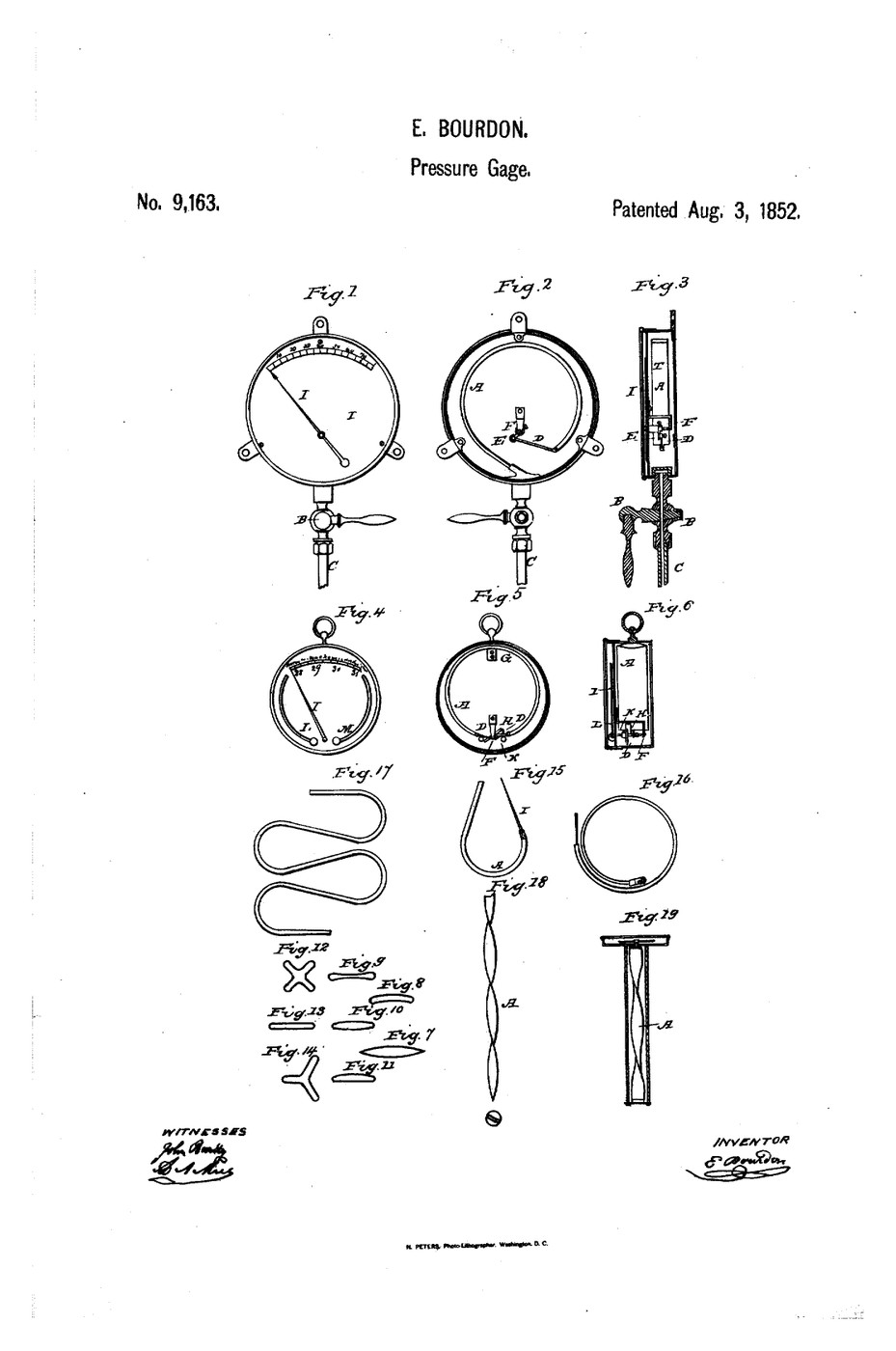


Bourdon Pressure Gauge
Every machine in this batch makes pressure. None of them tells you how much. Before Bourdon, the honest answers were a mercury column — which needs about ten metres of glass to read a boiler — or a weighted piston, which is accurate, slow, and destroyed by the first pressure surge.
Bourdon's gauge is a flattened metal tube bent into a C, sealed at the free end. Its cross-section is an oval. Admit pressure and the oval tries to become a circle, because a circle encloses the most area for a given perimeter and pressure pushes outward everywhere at once.
Here is the part worth pausing on: making the section rounder makes it taller in the plane of the bend, and a curved tube whose section grows taller must uncoil to accommodate it. So a pressure acting equally in all directions produces motion in one direction. The tip's movement is tiny — often under a millimetre — so a link drives a toothed sector, the sector drives a pinion on the needle shaft, and a hairspring keeps the teeth loaded on one flank so backlash never shows.
The result reads instantly, survives being dropped, costs almost nothing, and needs no power. It is why a pressure gauge looks the same on a 19th-century locomotive and a modern scuba tank.
Eugène Bourdon — French patent 18 June 1849; US 9,163, "Pressure Gage", granted 3 August 1852.
Instructions
Hold a Bourdon tube you already own
Hold a Bourdon tube you already own
Take a coiled paper party blower — the kind that unrolls when you blow it.
Look at it closely: a flattened tube, coiled, sealed at the far end. Blow into it and it uncoils; stop and it rolls back up.
That is a Bourdon tube. The only differences in a real gauge are that the tube is metal so it returns elastically instead of by paper stiffness, and that it is bent through about 270° instead of several turns.
Note which way it moves. Pressure always uncoils — never the reverse.
Materials for this step:
 Coiled Paper Party Blower1 piece
Find out why a round section is the whole mechanism
Find out why a round section is the whole mechanism
Flatten a short length of soft tubing between finger and thumb and measure its height across the flattened direction with the caliper. Then let it relax to round and measure again.
Expect the round section to be taller, even though the perimeter has not changed.
Now picture that tube bent into a C. The outer wall of the bend is longer than the inner wall. If the section grows taller, the two walls can no longer sit at their old radii — so the C must open out.
Pressure does not push the tip. It changes the tube's shape, and the bend converts that into travel.
Materials for this step:
 Silicone Tubing (6mm ID)1 m
Tools needed:
 Digital Caliper 6-Inch
Open a real gauge and find the amplification
Open a real gauge and find the amplification
Remove the bezel from a scrap gauge and identify the train: tube tip → link → toothed sector → pinion on the needle shaft, with a fine hairspring wound round the shaft.
Move the tip by hand through its full travel and measure the distance. Then count how far the needle sweeps.
Compute the ratio. Expect something like 200:1 to 500:1 — a fraction of a millimetre becoming most of a circle.
Then find the hairspring's job: push the needle backwards gently and feel it resist. It holds the sector against one side of the pinion teeth, so the gear lash that would otherwise make the needle wander is never taken up in the wrong direction.
Materials for this step:
 Scrap Bourdon Pressure Gauge1 piece
Tools needed:
Digital Caliper 6-InchMeasure hysteresis by approaching from both sides
Measure hysteresis by approaching from both sides
Fit the gauge to a hand pump. Raise the pressure to a chosen mark and read the needle. Now raise it well past that mark, and come back down to the same pressure. Read again.
Expect a small but real difference. That is hysteresis — the tube and the gear train do not retrace their path exactly.
Repeat near the very bottom and the very top of the dial. Expect the error to be worst at the extremes.
This is the measured reason behind the standard workshop rule: choose a gauge so the pressure you care about falls in the middle half of the dial. A gauge working at 5% or 95% of range is being read where it is least trustworthy.
Overpressure a scrap gauge and watch zero move
Overpressure a scrap gauge and watch zero move
On a gauge you are willing to destroy, and behind eye protection, drive the pressure past full scale until the needle stops against the peg. Release it fully.
Expect the needle not to return to zero.
The tube has been strained past its elastic limit and taken a permanent set. It is now a smoothly-working, confident-looking instrument that is wrong at every point on the dial.
This is the failure mode that matters most in practice, because nothing about it looks broken. A gauge whose needle does not rest exactly on zero when vented is telling you it has been overpressured, and every reading it has given since is suspect.
History & Context
History & Context
The patents. Eugène Bourdon (1808–1884), a Paris instrument maker, patented the gauge in France on 18 June 1849 and in the United States as US 9,163, "Pressure Gage", granted 3 August 1852. He founded his own works in 1850 to build them, and the firm still carries his name. Edward Ashcroft bought the American rights in 1852 and became the dominant US manufacturer — which is why the same instrument is called a Bourdon gauge in Europe and often an Ashcroft gauge in American workshops.
Why it arrived exactly when it did. The 1840s were the decade of boiler explosions. Steam pressure was rising, and operators had no continuous way to see what their vessel was holding — a safety valve tells you only that you have already reached the limit. Bourdon's gauge made pressure visible, continuously, on the boiler front. It belongs with the safety valve, not in competition with it: one warns, the other acts.
What it actually measures. The case is open to atmosphere, so the tube responds to the difference between inside and outside. A Bourdon gauge reads gauge pressure, and a reading of zero means "the same as the air around me", not "a vacuum". Absolute pressure needs a sealed reference, which is a different instrument — and the confusion between the two is a routine source of error in real calculations.
Refinements that followed. Spiral and helical tubes for more travel and finer resolution; glycerine filling to damp needle flutter on pumps and compressors, which is why so many hydraulic gauges are full of clear liquid; diaphragm seals so a steel tube never touches a corrosive or a food product; and snubbers to protect the tube from the surges of step 5.
Why it survives the electronic age. A piezoresistive transducer is more accurate and can be logged. It also needs power, and reads nothing when the power fails. A Bourdon tube needs none, fails visibly, and can be read across a room. Nearly every pressurised system built today carries both.
Materials
3- 1 piecePlaceholder
- Placeholder
- 1 piecePlaceholder
Tools Required
1- Placeholder
Connected Blueprint Materials

Related Blueprints
These blueprints share knowledge with this one — techniques, materials, or principles that connect them in the learning graph.


CC0 Public Domain
This blueprint is released under CC0. You are free to copy, modify, distribute, and use this work for any purpose, without asking permission.
Support the Maker by purchasing products through their Blueprint where they earn a Maker Commission set by Vendors, or create a new iteration of this Blueprint and include it as a connection in your own Blueprint to share revenue.