Collaboration
ART
BEAUTY & WELLNESS
CRAFT
CULTURE & HISTORY
ENTERTAINMENT
ENVIRONMENT
FOOD & DRINKS
REVERSE ENGINEERING
SCIENCES
SPORTS
TECHNOLOGY
WEARABLES
Shifting-Gear Grinding-Disk Churn: One Crank Wheel Is Thrown Into Gear With the Wings Below, the Grinding Disk Above, or Both
Buttercup

Created by

Buttercup

12. November 2026IE
0
0
0
0
0

Shifting-Gear Grinding-Disk Churn: One Crank Wheel Is Thrown Into Gear With the Wings Below, the Grinding Disk Above, or Both

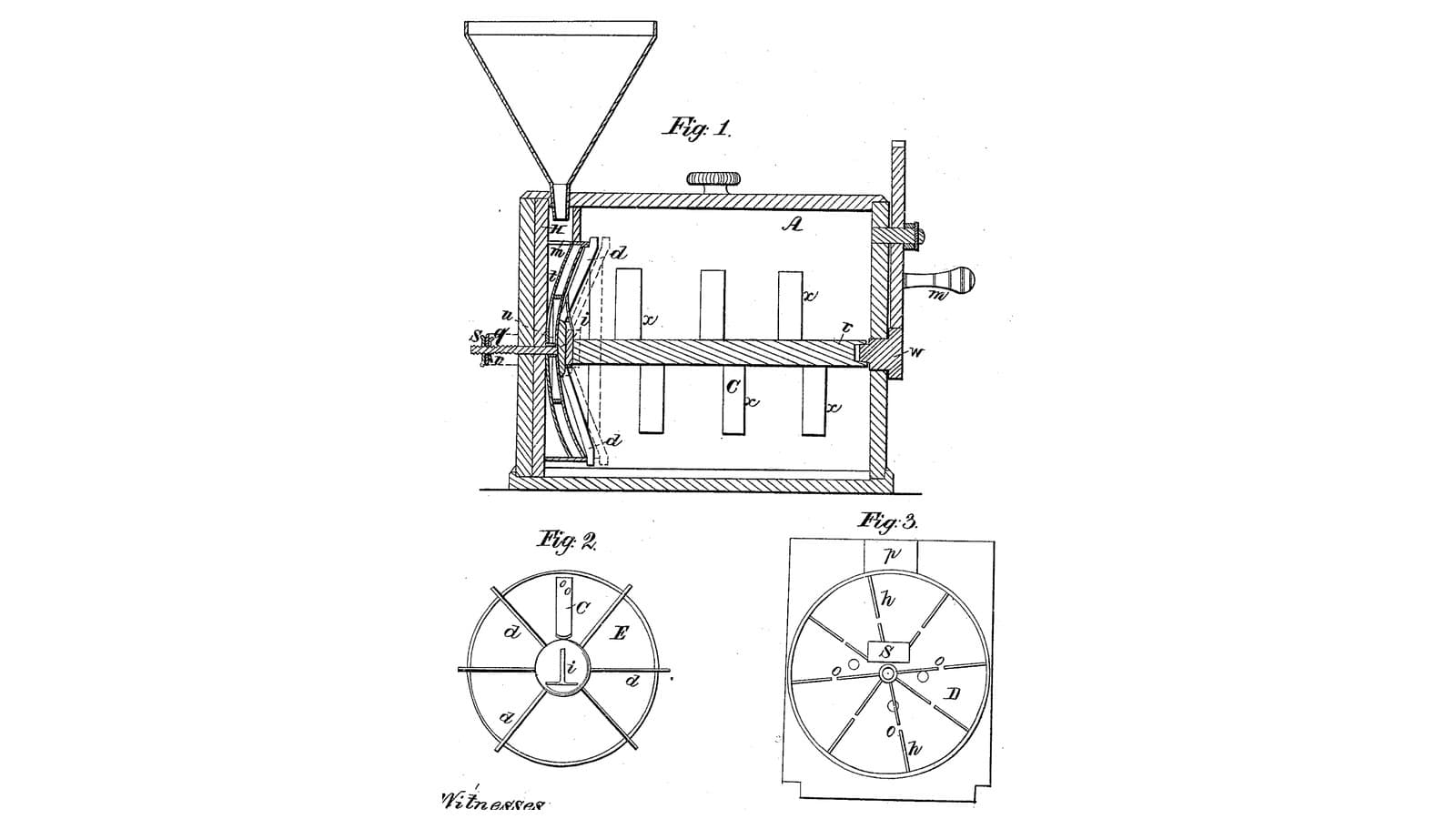
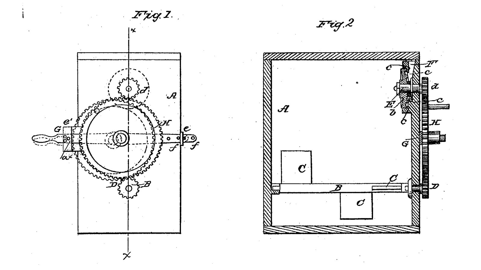
John Fowler and W. L. Walter of Homer, New York, received US 32,939, dated 30 July 1861, for a box churn with two working parts on one crank. High in the box a turning disk grinds the cream poured from a hopper against a fixed ribbed disk, and the cream falls below, out of their way; low in the box a shaft of wings gathers the butter. The crank wheel rides on a bar that slides and tilts in two guides on the box's side, so it can be put in gear with the disk alone, the wings alone, or both, and pinned there. The patent gives no sizes; every size here is ours.
Advanced
About 3 days

Instructions

1

One wheel, two pinions

Loading Jupyter Notebook...
2

Cream ground once between disks as it is poured in, three months before

Jackson and Clarke grind the cream in a disk pack over the beaters. Fowler and Walter put the disks to one side and let one crank drive either disks or wings.
3

Read US 32,939

"By having the wheel H, attached to the bar G, and the latter arranged as shown, the disk b, may be rotated without the shaft B, or the latter may be rotated without the former or both rotated simultaneously as may be desired. This is an important feature of the invention for it is frequently necessary to use the disks without the wings or gatherers and vice versa."
4

Body A and lid

Glue up a hardwood box A 300 mm wide, 360 long and 320 deep inside, from 20 mm boards, joints sealed with silicone sealant. Bore one end 16.6 mm at 80 and 240 mm above the inside floor on its centre line for the shafts B and E, and the far end 16.6 mm at 80 mm for B's other bearing. Cut a hardwood lid with a 14 mm hole 25 mm off the centre line and 13 mm in from the geared end, for the hopper's spout.

Materials for this step:

Hardwood BoardHardwood Board4 pieces
Wood GlueWood Glue1 piece
Silicone SealantSilicone Sealant1 piece
Wood ScrewsWood Screws30 pieces

Tools needed:

Table SawTable Saw
Cordless DrillCordless Drill
Drill Bit SetDrill Bit Set
Spade Bit SetSpade Bit Set
Bar ClampBar Clamp
Screwdriver SetScrewdriver Set
Tape MeasureTape Measure
5

Shaft B with wings C and pinion D

Cut a 16 mm stainless shaft B 432 mm long. Screw two pairs of hardwood wings C 70 x 80 x 20 mm through hardwood hubs on it, a quarter turn apart, one pair 70 to 150 mm from the geared end and one 220 to 300. Run it through both ends with shaft collars and pin a pinion D on its outer end 6 mm outside the box.

Materials for this step:

Stainless Steel RodStainless Steel Rod1 piece
Hardwood BoardHardwood Board1 piece
Wood ScrewsWood Screws8 pieces
Shaft CollarShaft Collar2 pieces
Split PinSplit Pin2 pieces
PETG FilamentPETG Filament1 piece

Tools needed:

FDM 3D PrinterFDM 3D Printer
Table SawTable Saw
Cordless DrillCordless Drill
Drill Bit SetDrill Bit Set
HacksawHacksaw
Files (Hand File)Files (Hand File)
Screwdriver SetScrewdriver Set
6

Print the pinions D and d (two)

A pinion: 16 teeth, module 2.5, 12 mm thick, 16.2 mm bore. Print two. PETG, 0.2 mm layers, 30 % infill, 4 walls.
Design FileSTLCC0 - Free
7

Print the grinding disk b

The turning disk: 110 mm across, 6 thick, with two rings of ledges c 3 mm high at 40 and 50 mm out on its face, 16.2 mm bore. PETG, 0.2 mm layers, 30 % infill, 4 walls.
Design FileSTLCC0 - Free
8

Print the hopper F

The hopper: a funnel 80 mm across on a 14 mm spout long enough to reach behind the fixed disk. PETG, 0.2 mm layers, 30 % infill, 4 walls.
Design FileSTLCC0 - Free
9

Disks a and b, shaft E, pinion d and hopper F

Cut a 6 mm HDPE disk a 120 mm across with a 60 mm centre opening, glue twelve HDPE ribs 26 x 6 x 3 mm radially on its face, and screw it inside the geared end on three 10 mm stainless standoffs 25 mm long, around the upper shaft hole, ribs inward. Cut a 16 mm stainless shaft E 120 mm long, push it through the end and the disk a's opening, pin the disk b on its inner end with its ledges 3 mm from a's ribs, and the pinion d on its outer end. Set the hopper F in the lid so its spout drops into the space behind a, beside the shaft.

Materials for this step:

HDPE SheetHDPE Sheet1 piece
Wood GlueWood Glue1 piece
Stainless Steel RodStainless Steel Rod2 pieces
Wood ScrewsWood Screws3 pieces
Split PinSplit Pin2 pieces
Shaft CollarShaft Collar1 piece
PETG FilamentPETG Filament1 piece

Tools needed:

FDM 3D PrinterFDM 3D Printer
CompassCompass
JigsawJigsaw
Spade Bit SetSpade Bit Set
HacksawHacksaw
Cordless DrillCordless Drill
Drill Bit SetDrill Bit Set
Screwdriver SetScrewdriver Set
10

Print the crank wheel H

The crank wheel: 48 teeth, module 2.5, 12 mm thick, 12.2 mm bore. PETG, 0.2 mm layers, 30 % infill, 4 walls.
Design FileSTLCC0 - Free
11

Bar G, guides e, e', wheel H and pin a*

Cut a mild steel flat bar G 470 x 24 x 6 mm, drill it 12.2 mm for H's axle 210 mm from one end and a row of 6 mm holes near the other end. Make two hardwood guides: e, a block with a slot just wide enough for the bar, screwed to the geared end level with the gap between the pinions; e', with a slot 60 mm tall so the bar's end can rise and fall, and a row of 6 mm holes across it. Fit a 12 mm stainless axle in the bar, the wheel H on it between the two pinions, and a crank handle on H's face. Slide the bar into the guides and hold it with a 6 mm pin a* through e' and the bar.

Materials for this step:

Mild Steel Flat BarMild Steel Flat Bar1 piece
Hardwood BoardHardwood Board1 piece
Wood ScrewsWood Screws8 pieces
Stainless Steel RodStainless Steel Rod1 piece
Split PinSplit Pin2 pieces
Hardwood DowelsHardwood Dowels1 piece
PETG FilamentPETG Filament1 piece

Tools needed:

FDM 3D PrinterFDM 3D Printer
HacksawHacksaw
Files (Hand File)Files (Hand File)
Bench ViseBench Vise
Cordless DrillCordless Drill
Drill Bit SetDrill Bit Set
Chisel Set - WoodChisel Set - Wood
Screwdriver SetScrewdriver Set
12

The build in 3D

FreeCAD model of this build, half the box cut away: the wing shaft low in the box, the fixed ribbed disk and the turning ledged disk high at the geared end, the hopper, and outside the crank wheel on its bar in two guides, meshing both pinions.
Design FileBLENDCC0 - Free
13

Churn: grind, then gather

Pin the bar so H meshes the disk's pinion d only. Turn the crank and pour about 12 litres of heavy cream at about 15 °C, checked with the thermometer, slowly into the hopper, timing it; it is ground between the disks and falls to the bottom. Then move the bar so H meshes the wings' pinion D (or both) and turn to gather the butter. Lift the lid, take out the butter, pour the buttermilk into a bowl, wash the butter in cold water until it runs clear, salt and weigh it.

Materials for this step:

Heavy CreamHeavy Cream12 l
Coarse Sea SaltCoarse Sea Salt1 piece
WaterWater1 piece

Tools needed:

Leave-In Probe ThermometerLeave-In Probe Thermometer
StopwatchStopwatch
Digital Kitchen ScaleDigital Kitchen Scale
Stainless Steel Mixing Bowl (Large)Stainless Steel Mixing Bowl (Large)
14

Troubleshooting

Shifting-gear churn troubleshooting.

Flow

Loading...
15

History and honest limits

**John Fowler** and **W. L. Walter** of Homer, Cortlandt County, New York, US 32,939, 30 July 1861, "Churn". They did not claim the disks or the wings, which were known, but "the arrangement of the sliding or adjustable bar G, with the wheel H, attached and arranged in relation with the pinions D, d, of the shaft B, and disk b". Their drawing shows H's crank as a pin on its face and a handle on the bar's end for shifting it. The patent gives no sizes; every size here is ours.

Materials

14

Tools Required

18

Design Files

5

CC0 Public Domain

This blueprint is released under CC0. You are free to copy, modify, distribute, and use this work for any purpose, without asking permission.

Support the Maker by purchasing products through their Blueprint where they earn a Maker Commission set by Vendors, or create a new iteration of this Blueprint and include it as a connection in your own Blueprint to share revenue.

Discussion

(0)

Log in to join the discussion

Loading comments...