Collaboration
ART
BEAUTY & WELLNESS
CRAFT
CULTURE & HISTORY
ENTERTAINMENT
ENVIRONMENT
FOOD & DRINKS
REVERSE ENGINEERING
SCIENCES
SPORTS
TECHNOLOGY
WEARABLES
Atmospheric Combination Churn: A Fan Sends Air Down a Hollow Shaft and Out Through the Turning Arm
Buttercup

Created by

Buttercup

10. November 2026IE
0
0
0
0
0

Atmospheric Combination Churn: A Fan Sends Air Down a Hollow Shaft and Out Through the Turning Arm

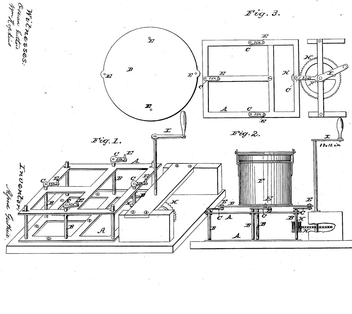
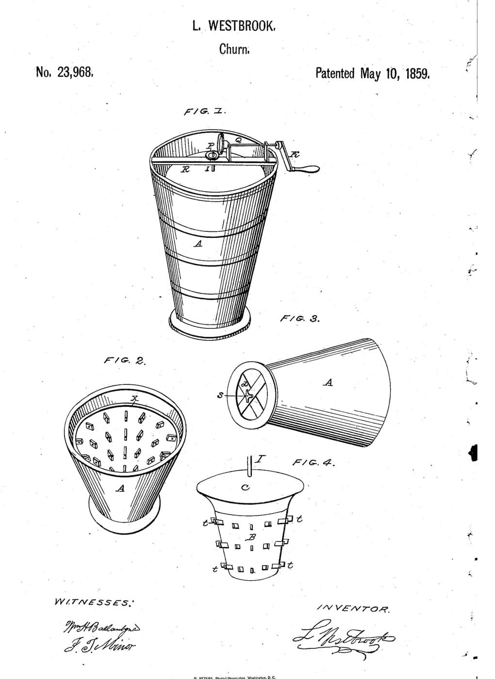
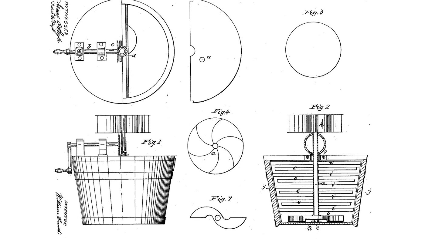
William Smith Hall of Quincy, Massachusetts, received US 24,934, dated 2 August 1859, for what he called the "Atmospheric Combination-Churn". A crank on the cover turns a hollow upright shaft three times as fast through a large wheel and a pinion. A fan on the shaft's top takes in air, which goes down the shaft and out through a hollow arm at the bottom, while solid paddles on the shaft swing the cream past a rack of fixed bars. This rung builds it in a 20-litre bucket with printed parts. Hall gives no sizes but the 3:1 wheel; every other size is ours.
Intermediate
About 2 days, plus printing

Instructions

1

When does air come out of the hollow arm?

Loading Jupyter Notebook...
2

Air through the cream, before it

That churn pushed air down a hollow staff by hand. Hall's turns, and a fan feeds the air.
3

Read US 24,934

"By a rapid rotary motion of the hollow shaft from right to left, which is produced by the driving wheel being three times the size of the pinion, the air is forced into the fan down through the hollow shaft, while the curve of the hollow arm or paddle at the bottom of the shaft being in an opposite direction from the arms of the fan, a vacuum is created, which allows the air to be discharged, causing a vertical action on the milk or cream".
4

Print the hollow arm b

Two hollow half-discs (48 mm radius, 24 mm deep) on a hub that takes the 16 mm tube, their straight faces open on opposite sides as Fig. 7 draws, with the point c under the hub. Print it hub down with tree supports and pull them out through the open faces. PETG, 0.2 mm layers, 40 % infill, 4 walls.
Design FileSTLCC0 - Free
5

Print the cup d

The 60 mm cup with a cone recess for the point, a trap for an M6 nut underneath and a groove for an O-ring about 30 mm across on a 2 mm cord. PETG, 0.2 mm layers, 40 % infill, 4 walls.
Design FileSTLCC0 - Free
6

Print the paddles e

One solid paddle: a split hub for the 16 mm tube with an M5 clamp bolt, and a blade 24 mm tall reaching 96 mm. Print four. PETG, 0.2 mm layers, 40 % infill, 4 walls.
Design FileSTLCC0 - Free
7

Print the pinion g

The 12-tooth spur pinion (module 2) with a hub, bored for the 16 mm tube and cross-drilled for a pin. PETG, 0.2 mm layers, 40 % infill, 4 walls.
Design FileSTLCC0 - Free
8

Print the driving wheel c

The 36-tooth crown wheel (module 2, three times the pinion) with its hub, bored for the 12 mm crank shaft and cross-drilled for a pin. Print it teeth up. PETG, 0.2 mm layers, 40 % infill, 4 walls.
Design FileSTLCC0 - Free
9

Print the fan's upper disc

The plain 160 mm disc (Fig. 3) with the six curved arms standing on it (Fig. 4). Print it disc down. PETG, 0.2 mm layers, 40 % infill, 4 walls.
Design FileSTLCC0 - Free
10

Print the fan's lower disc

The 160 mm disc with the centre hole (Fig. 4, a) on a split hub that clamps to the tube's top with an M5 bolt, Hall's "screw". PETG, 0.2 mm layers, 40 % infill, 4 walls.
Design FileSTLCC0 - Free
11

Cup d in the bucket's floor

Drill a 6.5 mm hole in the middle of the bucket's floor. Push an M6 nut into the cup's trap and lay the O-ring in its groove. Stand the cup over the hole and bolt it from underneath with a stainless M6 x 16 bolt and a washer, just tight enough to squeeze the O-ring. Fill the bucket with water to check it does not leak, then empty it.

Materials for this step:

20-Liter Bucket20-Liter Bucket1 piece
Hex Bolt AssortmentHex Bolt Assortment1 piece
Hex NutHex Nut1 piece
Flat WasherFlat Washer1 piece
O-RingO-Ring1 piece

Tools needed:

Cordless DrillCordless Drill
Drill Bit SetDrill Bit Set
Adjustable SpannerAdjustable Spanner
WaterWater
12

Hollow shaft a, arm b and paddles e

Cut the stainless tube 507 mm long and deburr both ends. Press it 26 mm into the hollow arm's hub and check you can blow through the tube and out of both open faces. Clamp the four paddles on the tube with their middles 80, 140, 200 and 260 mm above the bucket's floor, each turned 45 degrees from the one below, with stainless M5 bolts and lock nuts. Stand the arm's point in the cup.

Materials for this step:

Stainless Steel TubeStainless Steel Tube1 piece
Hex Bolt AssortmentHex Bolt Assortment4 pieces
Nylon Insert Lock NutNylon Insert Lock Nut4 pieces
PETG FilamentPETG Filament1 piece

Tools needed:

FDM 3D PrinterFDM 3D Printer
HacksawHacksaw
Files (Hand File)Files (Hand File)
Adjustable SpannerAdjustable Spanner
Tape MeasureTape Measure
13

Rack of bars i on uprights j

Cut two hardwood uprights 30 x 20 mm, 366 mm long, and four bars 200 x 20 x 12 mm. Glue and screw the bars between the uprights' faces at 110, 170, 230 and 290 mm up, so the rack is 260 mm wide. Lower it into the bucket beside the shaft, the bars' middle line 25 mm from the shaft, and turn the shaft by hand: every paddle must pass between two bars.

Materials for this step:

Hardwood BoardHardwood Board1 piece
Wood GlueWood Glue1 piece
Wood ScrewsWood Screws8 pieces

Tools needed:

Hand SawHand Saw
Cordless DrillCordless Drill
Drill Bit SetDrill Bit Set
SandpaperSandpaper
Tape MeasureTape Measure
14

Cover, journal f, chair and crank

Cut a 320 mm disc of 12 mm plywood and saw it in half. Notch the front half 24 mm across and the back half 50 mm across at the middle of the cut, as Fig. 6 draws, and bore a 24 mm air opening in the back half 90 mm from the middle. On the front half screw a hardwood block 80 x 56 x 30 mm over the notch, bored 17 mm for the tube, and two bearing blocks 44 x 30 mm, 110 mm tall, their near faces 45 and 115 mm from the middle, bored 12.6 mm through 90 mm up. Slide a 190 mm stainless rod through them for the crank shaft, pin the driving wheel on its inner end and a hardwood crank arm with a dowel handle 88 mm out on the other.

Materials for this step:

Plywood SheetPlywood Sheet1 piece
Hardwood BoardHardwood Board1 piece
Hardwood DowelsHardwood Dowels1 piece
Stainless Steel RodStainless Steel Rod1 piece
Wood GlueWood Glue1 piece
Wood ScrewsWood Screws6 pieces

Tools needed:

JigsawJigsaw
Hand SawHand Saw
Cordless DrillCordless Drill
Spade Bit SetSpade Bit Set
Drill Bit SetDrill Bit Set
HacksawHacksaw
Tape MeasureTape Measure
15

Pinion g and fan h

Lay both cover halves on the bucket, the tube through the journal. Pin the pinion on the tube so its teeth mesh fully with the driving wheel, just above the journal. Glue the fan's two discs together, arms between, and clamp the fan on the tube's top. Turn the crank: the shaft turns three times for each turn, and you feel air drawn in at the fan's rim.

Materials for this step:

Wood GlueWood Glue1 piece
Hex Bolt AssortmentHex Bolt Assortment1 piece
Nylon Insert Lock NutNylon Insert Lock Nut1 piece

Tools needed:

Adjustable SpannerAdjustable Spanner
Cordless DrillCordless Drill
Drill Bit SetDrill Bit Set
16

The build in 3D

FreeCAD model of this build, cut open: the bucket, the cup and the hollow arm on the floor, the hollow shaft with four paddles passing between the rack of bars, the two-piece cover with its journal, chair and air opening, the driving wheel on the crank shaft turning the pinion, and the fan on top. The shaft was checked at 16 angles.
Design FileBLENDCC0 - Free
17

Churn

Pour about 10 litres of heavy cream at about 15 °C into the bucket, checked with the thermometer, and put the cover on. Turn the crank steadily, faster than the notebook's lowest speed, and time it. Lift the back half now and then to look. When the butter comes, lift the shaft and rack out, pour off the buttermilk, wash the butter in cold water until it runs clear, work in a pinch of salt and weigh it.

Materials for this step:

Heavy CreamHeavy Cream10 l
Coarse Sea SaltCoarse Sea Salt1 piece
WaterWater1 piece

Tools needed:

Leave-In Probe ThermometerLeave-In Probe Thermometer
StopwatchStopwatch
Digital Kitchen ScaleDigital Kitchen Scale
Stainless Steel Mixing Bowl (Large)Stainless Steel Mixing Bowl (Large)
18

Troubleshooting

Atmospheric churn troubleshooting.

Flow

Loading...
19

History and honest limits

**William Smith Hall** of Quincy, Massachusetts, US 24,934, 2 August 1859, "Churn". He claimed forcing a current of air through the milk or cream by the rotary fan combined with the upright hollow shaft, the rotary hollow and solid paddles and the stationary bars. He gives no sizes but the driving wheel three times the pinion, so every size here is ours: a crown wheel and pinion stand in for his wheel and pinion, and the fan, arm, paddles and rack are printed or cut to fit a 20-litre bucket. Our notebook is a rough upper-bound estimate, not a test.

Materials

17

Tools Required

16

Design Files

8

CC0 Public Domain

This blueprint is released under CC0. You are free to copy, modify, distribute, and use this work for any purpose, without asking permission.

Support the Maker by purchasing products through their Blueprint where they earn a Maker Commission set by Vendors, or create a new iteration of this Blueprint and include it as a connection in your own Blueprint to share revenue.

Discussion

(0)

Log in to join the discussion

Loading comments...