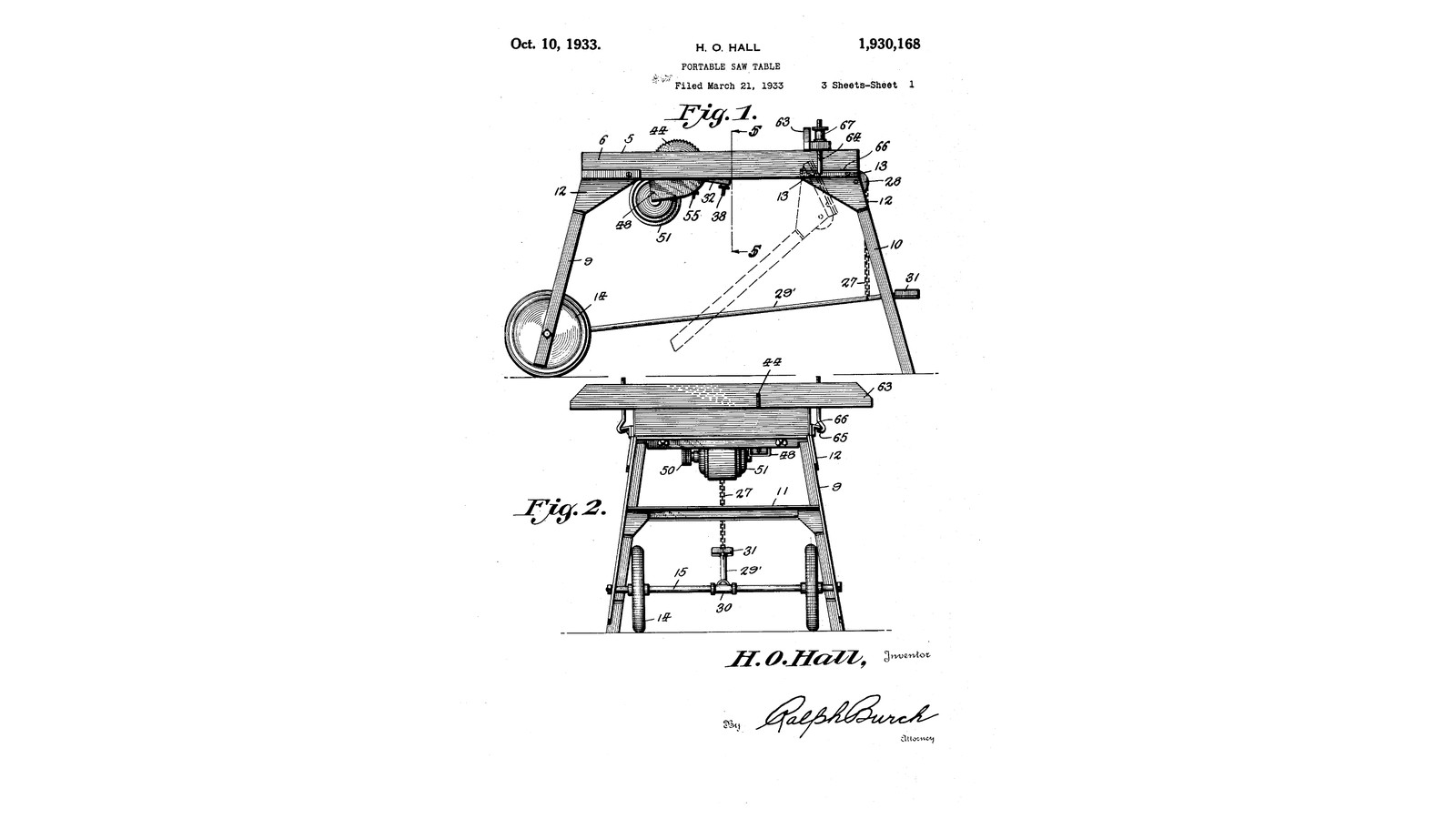

Foot-Fed Carriage Saw Table: The Saw Rides on Balls Under the Table, a Foot Lever Pulls It Through the Work (Hall, 1933)
Instructions
The foot lever, the travel and the cut
The foot lever, the travel and the cut
Read US 1,930,168
Read US 1,930,168
Table and legs
Table and legs
Materials for this step:
 Plywood Sheet1 piece
 Pine Lumber6 pieces
 Mild Steel Round Bar1 piece
 Rubber Wheel Set1 piece
 Carriage Bolt8 pieces
 Wood Screws40 pieces
 Wood Glue1 piece
Tools needed:
 Jigsaw
 Cordless Drill
 Drill Bit Set
 Bar Clamp
 Combination Square
 Tape Measure
Tracks and carriage
Tracks and carriage
Materials for this step:
Pine Lumber1 piece Mild Steel Angle Iron2 pieces
 Hex Bolt Assortment12 pieces
 Threaded Rod1 piece
 Hex Nut8 pieces
 Mild Steel Flat Bar1 piece
 Ball Bearings1 piece
 Extension Spring2 piecesWood Screws16 pieces
Tools needed:
 Hacksaw
 Angle Grinder
 Drill PressDrill Bit Set
 File Set
 Bench Vise
 Adjustable Spanner
 Safety Glasses
Foot lever and chain
Foot lever and chain
Materials for this step:
 Hardwood Board1 piece
 Pulley1 pieceMild Steel Round Bar1 piece
 Roller Chain1 pieceHex Bolt Assortment3 pieces
Tools needed:
JigsawCordless DrillDrill Bit SetHacksawAdjustable SpannerSaw frame, arbor and shield
Saw frame, arbor and shield
Materials for this step:
Mild Steel Angle Iron1 pieceMild Steel Round Bar2 pieces Cup Point Set Screw4 piecesThreaded Rod1 pieceHex Nut4 pieces
 Flange Bearing2 pieces
 Circular Saw Blade Set1 piece
 V-Belt Pulley (A-Section)1 piece
 Mild Steel Sheet1 pieceHex Bolt Assortment10 pieces
Tools needed:
HacksawAngle GrinderDrill PressDrill Bit Set Tap and Die Set
 Tap Wrench
 Metal Lathe
 Lathe Chuck 3-Jaw
 Lathe Cutting Tool
 Digital Caliper 6-Inch
 Tin SnipsBench ViseAdjustable Spanner
 Hex Key Set
Motor frame
Motor frame
Materials for this step:
Mild Steel Angle Iron1 piece Electric Motor1 pieceV-Belt Pulley (A-Section)1 piece
 V-Belt (A-Section)1 pieceMild Steel Round Bar1 pieceThreaded Rod1 piece
 Coil Spring1 piece
 Flat Washer2 piecesHex Nut2 piecesHex Bolt Assortment6 pieces
 On/Off Switch1 piece
Tools needed:
HacksawDrill PressDrill Bit SetAdjustable SpannerHex Key SetFence and first cut
Fence and first cut
Materials for this step:
Hardwood Board1 pieceThreaded Rod1 pieceHex Nut2 piecesMild Steel Flat Bar1 pieceWood Screws8 piecesTools needed:
JigsawCordless DrillDrill Bit SetCombination SquareSafety Glasses Hearing Protection (Ear Defenders, SNR 30 dB)
Troubleshooting
Troubleshooting
Flow
History and honest limits
History and honest limits
Materials
27- 1 piecePlaceholder
- 6 piecesPlaceholder
- 2 piecesPlaceholder
- 1 piecePlaceholder
- 8 piecesPlaceholder
- 64 piecesPlaceholder
- 1 piecePlaceholder
- 2 piecesPlaceholder
- 31 piecesPlaceholder
- 1 piecePlaceholder
- 16 piecesPlaceholder
- 1 piecePlaceholder
- 1 piecePlaceholder
- 2 piecesPlaceholder
- 1 piecePlaceholder
- 1 piecePlaceholder
- 1 piecePlaceholder
- 4 piecesPlaceholder
- 2 piecesPlaceholder
- 1 piecePlaceholder
- 1 piecePlaceholder
- 1 piecePlaceholder
- 1 piecePlaceholder
- 1 piecePlaceholder
- 1 piecePlaceholder
- 2 piecesPlaceholder
- 1 piecePlaceholder
Tools Required
22- 1 vendor sell this, none ship to you yetPlaceholder
- 1 vendor sell this, none ship to you yetPlaceholder
- Placeholder
- Placeholder
- Placeholder
- 1 vendor sell this, none ship to you yetPlaceholder
- Placeholder
- 1 vendor sell this, none ship to you yetPlaceholder
- Placeholder
- Placeholder
- Placeholder
- Placeholder
- Placeholder
- Placeholder
- Placeholder
- Placeholder
- Placeholder
- Placeholder
- Placeholder
- Placeholder
- Placeholder
This blueprint makes

Related Blueprints
These blueprints share knowledge with this one — techniques, materials, or principles that connect them in the learning graph.
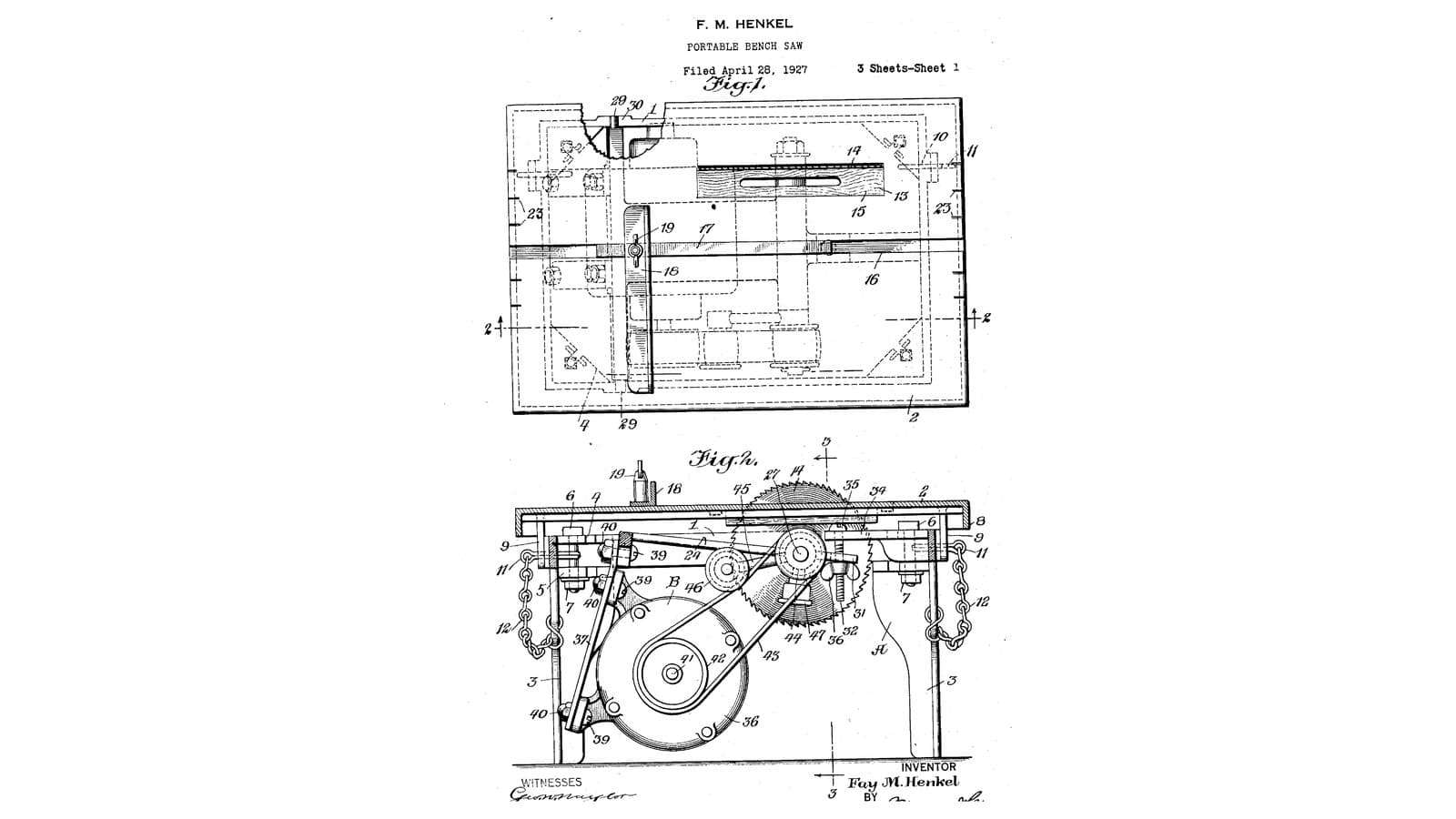
Portable Bench Saw: A Lift-Out Power Unit on Trunnions, Its Motor on Spring Bars, Under a Tilting Platform (Henkel, 1928)
by Forge
Woodworking
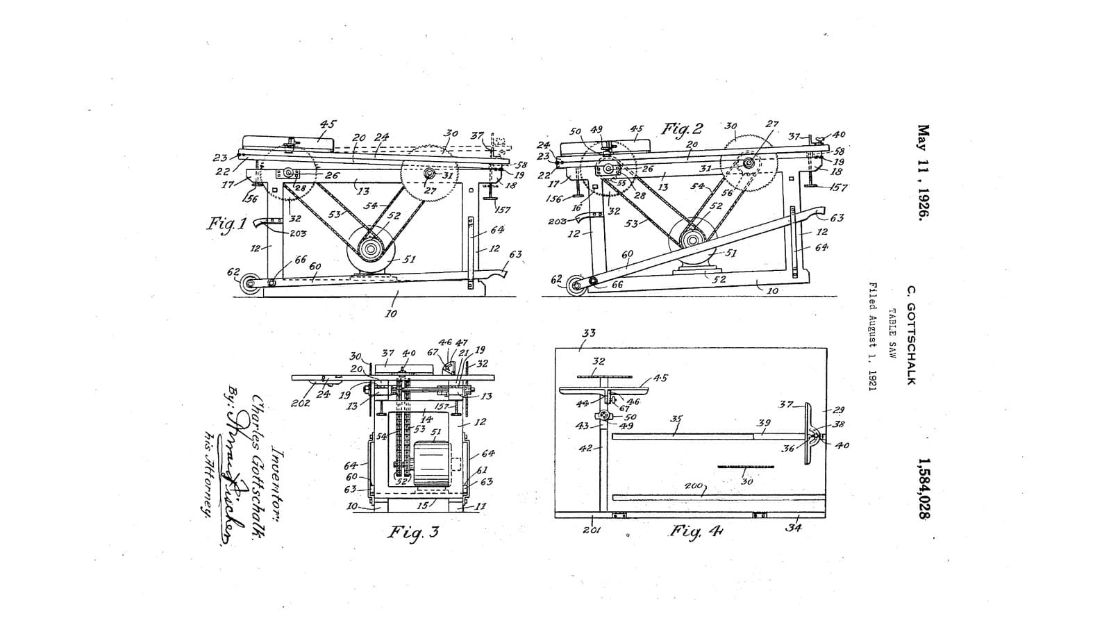
Twin-Saw Table: A Rip Saw and a Crosscut Saw at Opposite Corners, One Motor, Each Depth Set by Tilting the Top (Gottschalk, 1926)
by Forge
Woodworking
CC0 Public Domain
This blueprint is released under CC0. You are free to copy, modify, distribute, and use this work for any purpose, without asking permission.
Support the Maker by purchasing products through their Blueprint where they earn a Maker Commission set by Vendors, or create a new iteration of this Blueprint and include it as a connection in your own Blueprint to share revenue.