Collaboration
ART
BEAUTY & WELLNESS
CRAFT
CULTURE & HISTORY
ENTERTAINMENT
ENVIRONMENT
FOOD & DRINKS
REVERSE ENGINEERING
SCIENCES
SPORTS
TECHNOLOGY
WEARABLES
Counter-Turning Hooped Beater Churn: One Bevel Wheel Turns a Spindle and a Hollow Shaft Opposite Ways, Spiral Hoops Sweep the Wall
Buttercup

Created by

Buttercup

11. November 2026IE
0
0
0
0
0

Counter-Turning Hooped Beater Churn: One Bevel Wheel Turns a Spindle and a Hollow Shaft Opposite Ways, Spiral Hoops Sweep the Wall

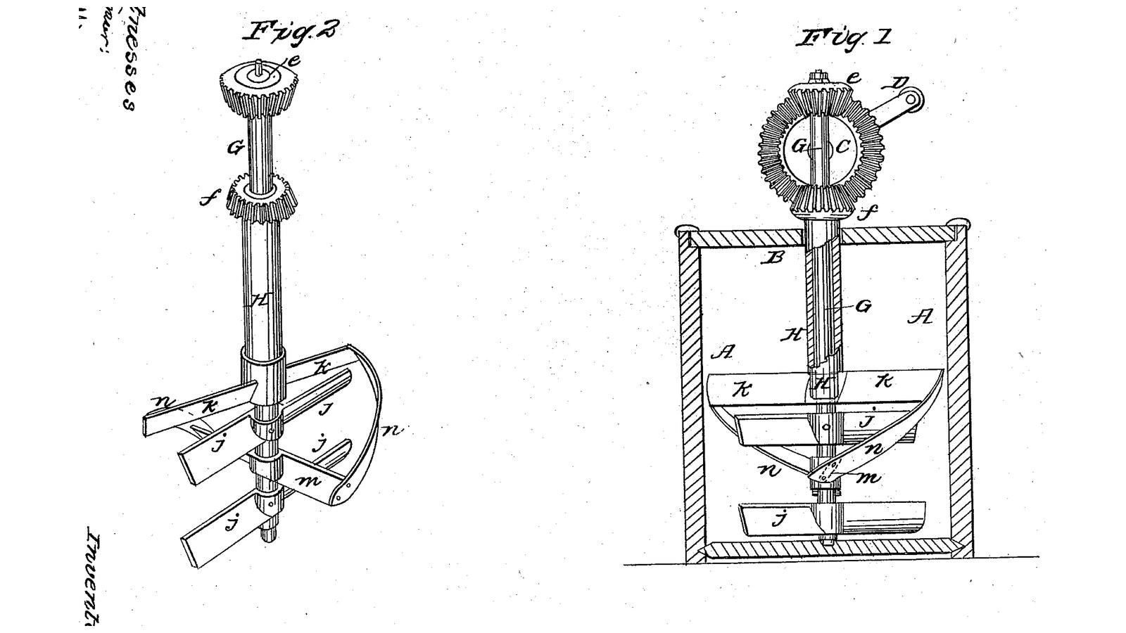
William Bently Hopkins of Oakfield, New York, received US 31,806, dated 26 March 1861, for a churn whose crank turns one bevel wheel between two pinions, one above and one below, so a spindle and a hollow shaft round it turn opposite ways. The spindle carries two slats; the hollow shaft carries a slat at its foot and, through two hoops that spiral a quarter turn down beside the wall, a second slat between the spindle's two. The hoops sweep back the cream that would lodge against the wall. The cover lifts off with the gearing and the beaters come out. The patent gives no sizes; every size here is ours.
Intermediate
About 2 days

Instructions

1

Two sets turning against each other

Loading Jupyter Notebook...
2

Parts turning opposite ways in one churn, a year before

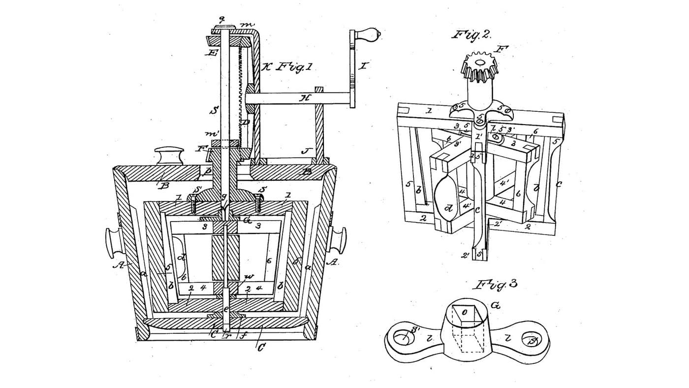
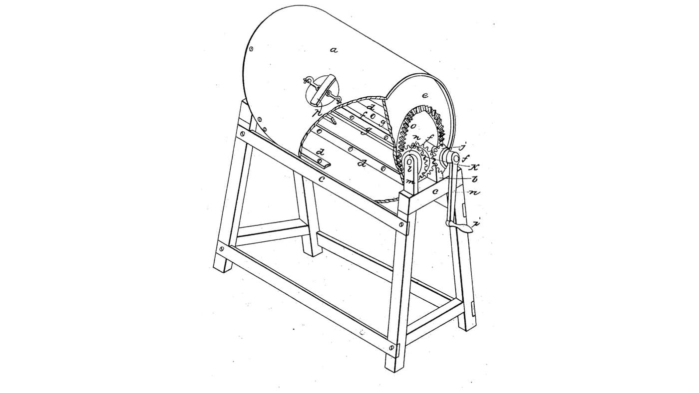
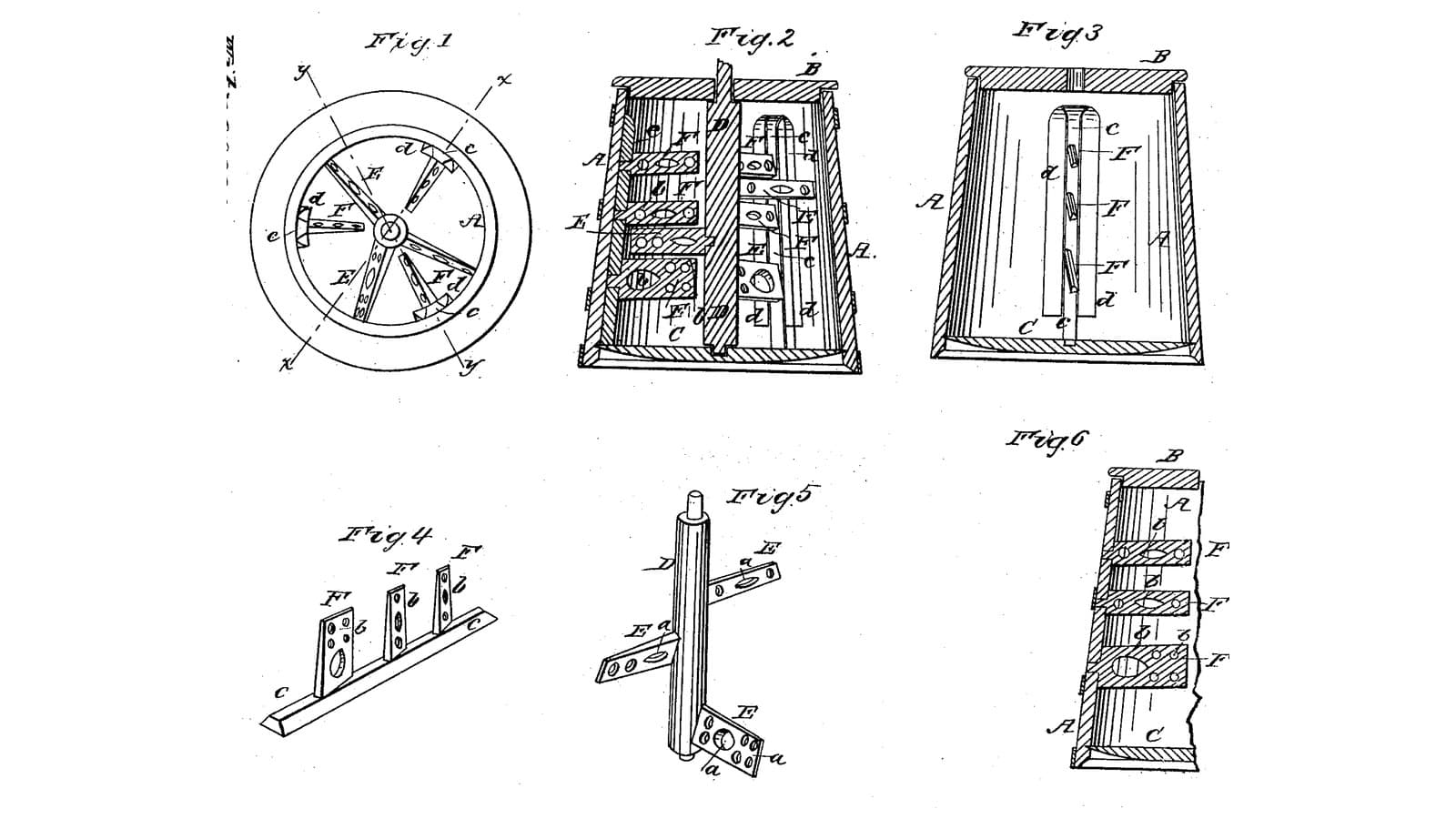
Ward turns a ribbed cylinder one way and dashers the other. Hopkins turns two sets of beaters on a spindle and a hollow shaft from one bevel wheel.
3

Read US 31,806

"The hoops n n ... not only maintain the relative position between k and m, but have a specific effect in displacing and agitating that portion of the milk or cream which would, by the operation of the two sets of beaters, be forced and impacted against the walls of the vessel, where they would, if allowed to remain, escape the action of the beaters, to a considerable extent."
4

Print the step

The step on the bucket's floor: 40 mm across, 12 high, with a 12.8 mm hole 8 deep. PETG, 0.2 mm layers, 30 % infill, 4 walls.
Design FileSTLCC0 - Free
5

Body A and cover B

Use a 20-litre food-grade bucket as the body A and set the printed step in the middle of its floor. Cut a 12 mm HDPE cover B to its top, bore it 23 mm at the centre, and saw it across through the hole into two halves.

Materials for this step:

20-Liter Bucket20-Liter Bucket1 piece
HDPE SheetHDPE Sheet1 piece
PETG FilamentPETG Filament1 piece

Tools needed:

FDM 3D PrinterFDM 3D Printer
CompassCompass
JigsawJigsaw
Spade Bit SetSpade Bit Set
Cordless DrillCordless Drill
6

Spindle G and slats j

Cut a 12 mm stainless spindle G 580 mm long. Plane two hardwood slats j 220 x 30 x 8 mm, bore each 12.2 mm at the middle with a hardwood hub, and pin them on the spindle 30 and 130 mm above its foot, a quarter turn apart, each tilted 20 degrees about its length.

Materials for this step:

Stainless Steel RodStainless Steel Rod1 piece
Hardwood BoardHardwood Board1 piece
Hardwood DowelsHardwood Dowels1 piece
Wood GlueWood Glue1 piece

Tools needed:

Table SawTable Saw
Cordless DrillCordless Drill
Drill Bit SetDrill Bit Set
HacksawHacksaw
Files (Hand File)Files (Hand File)
7

Hollow shaft H, slats k and m, hoops n

Cut a 22 mm stainless tube H 270 mm long. Plane two hardwood slats k and m 250 x 30 x 8 mm, tilted 20 degrees the other way. Fix k on the tube's foot with a hardwood hub. Bore m 13.2 mm at its hub so it turns loose on the spindle, and slide it on between the two j slats. Bend two strips of stainless strip 20 mm wide into hoops n that run a quarter turn round at 124 mm radius while dropping 100 mm, and screw each from an end of k down to the end of m a quarter turn round, so m lies at right angles to k. Slide the tube down over the spindle.

Materials for this step:

Stainless Steel TubeStainless Steel Tube1 piece
Hardwood BoardHardwood Board1 piece
Cold-Rolled Stainless Steel Strip (420)Cold-Rolled Stainless Steel Strip (420)1 piece

Wood ScrewsWood Screws8 pieces
Wood GlueWood Glue1 piece

Tools needed:

Table SawTable Saw
Cordless DrillCordless Drill
Drill Bit SetDrill Bit Set
HacksawHacksaw
Tin SnipsTin Snips
Bench ViseBench Vise
Rubber MalletRubber Mallet
Screwdriver SetScrewdriver Set
8

Print the pinion f

The lower pinion f on the hollow shaft: 14 teeth, module 2.5, 22.2 mm bore. PETG, 0.2 mm layers, 30 % infill, 4 walls.
Design FileSTLCC0 - Free
9

Print the pinion e

The upper pinion e on the spindle: 14 teeth, module 2.5, 12.2 mm bore; fit it hub up. PETG, 0.2 mm layers, 30 % infill, 4 walls.
Design FileSTLCC0 - Free
10

Print the driving wheel C

The driving wheel C: a crown wheel of 42 teeth, module 2.5, 16.2 mm bore. PETG, 0.2 mm layers, 30 % infill, 4 walls.
Design FileSTLCC0 - Free
11

Frame, wheel C, pinions e and f, crank D

Screw two hardwood posts 30 x 40 mm, 195 tall, to the cover either side of its centre, 150 mm apart over their inner faces, and join their tops with a top bar bored 12.6 mm over the centre. Screw two hardwood bearing blocks 50 x 25 mm, 120 tall, to the cover 60 and 125 mm in front of the centre, bored 16.6 mm across 96 mm above the cover. Pin the pinion f on the hollow shaft 40 mm above the cover and the pinion e on the spindle 105 mm above f, teeth facing each other. Run a 16 mm stainless shaft 150 mm long through the blocks with the crown wheel C pinned on its inner end between the two pinions, meshing both, a shaft collar, and a crank D of mild steel flat bar, 100 mm throw, with a hardwood handle.

Materials for this step:

Hardwood BoardHardwood Board1 piece
Stainless Steel RodStainless Steel Rod1 piece
Shaft CollarShaft Collar1 piece
Split PinSplit Pin4 pieces
Mild Steel Flat BarMild Steel Flat Bar1 piece
Hardwood DowelsHardwood Dowels1 piece
Wood ScrewsWood Screws12 pieces
PETG FilamentPETG Filament1 piece

Tools needed:

FDM 3D PrinterFDM 3D Printer
Table SawTable Saw
Cordless DrillCordless Drill
Drill Bit SetDrill Bit Set
HacksawHacksaw
Files (Hand File)Files (Hand File)
Bench ViseBench Vise
Screwdriver SetScrewdriver Set
12

The build in 3D

FreeCAD model of this build, the bucket cut open: the step, the spindle with its two slats, the hollow shaft with its slat, the loose slat and the two spiral hoops, the cover, posts and top bar, the crown wheel between the two pinions, and the crank.
Design FileBLENDCC0 - Free
13

Churn

Pour about 10 litres of heavy cream at about 15 °C, checked with the thermometer, into the bucket with the beaters in, lay on the cover halves and seat the gearing. Turn the crank steadily, timing it. When the butter comes, lift off the cover and gearing, lift out the beaters, take out the butter, pour the buttermilk into a bowl, wash the butter in cold water until it runs clear, salt and weigh it.

Materials for this step:

Heavy CreamHeavy Cream10 l
Coarse Sea SaltCoarse Sea Salt1 piece
WaterWater1 piece

Tools needed:

Leave-In Probe ThermometerLeave-In Probe Thermometer
StopwatchStopwatch
Digital Kitchen ScaleDigital Kitchen Scale
Stainless Steel Mixing Bowl (Large)Stainless Steel Mixing Bowl (Large)
14

Troubleshooting

Hooped-beater churn troubleshooting.

Flow

Loading...
15

History and honest limits

**Wm. Bently Hopkins** of Oakfield, Genesee County, New York, US 31,806, 26 March 1861, "Churn". He claimed "the beaters j j and k, m, the latter provided with spiral arms, n n", and did not claim beaters on separate shafts turning opposite ways as such. His text says the hoops run a quarter of the circle, putting m at right angles to k, and also that m is forty-five degrees in advance of k; we follow the hoops. His gearing was a bevel wheel between two bevel pinions; ours is a printed crown wheel. The patent gives no sizes; every size here is ours.

Materials

16

Tools Required

17

Design Files

5

CC0 Public Domain

This blueprint is released under CC0. You are free to copy, modify, distribute, and use this work for any purpose, without asking permission.

Support the Maker by purchasing products through their Blueprint where they earn a Maker Commission set by Vendors, or create a new iteration of this Blueprint and include it as a connection in your own Blueprint to share revenue.

Discussion

(0)

Log in to join the discussion

Loading comments...