Collaboration
ART
BEAUTY & WELLNESS
CRAFT
CULTURE & HISTORY
ENTERTAINMENT
ENVIRONMENT
FOOD & DRINKS
REVERSE ENGINEERING
SCIENCES
SPORTS
TECHNOLOGY
WEARABLES
Opposed Perforated-Paddle Churn: Sloping Holed Paddles on a Geared Shaft Pass Between Paddles Sloping the Other Way on Slide Bars
Buttercup

Created by

Buttercup

11. November 2026IE
0
0
0
0
0

Opposed Perforated-Paddle Churn: Sloping Holed Paddles on a Geared Shaft Pass Between Paddles Sloping the Other Way on Slide Bars

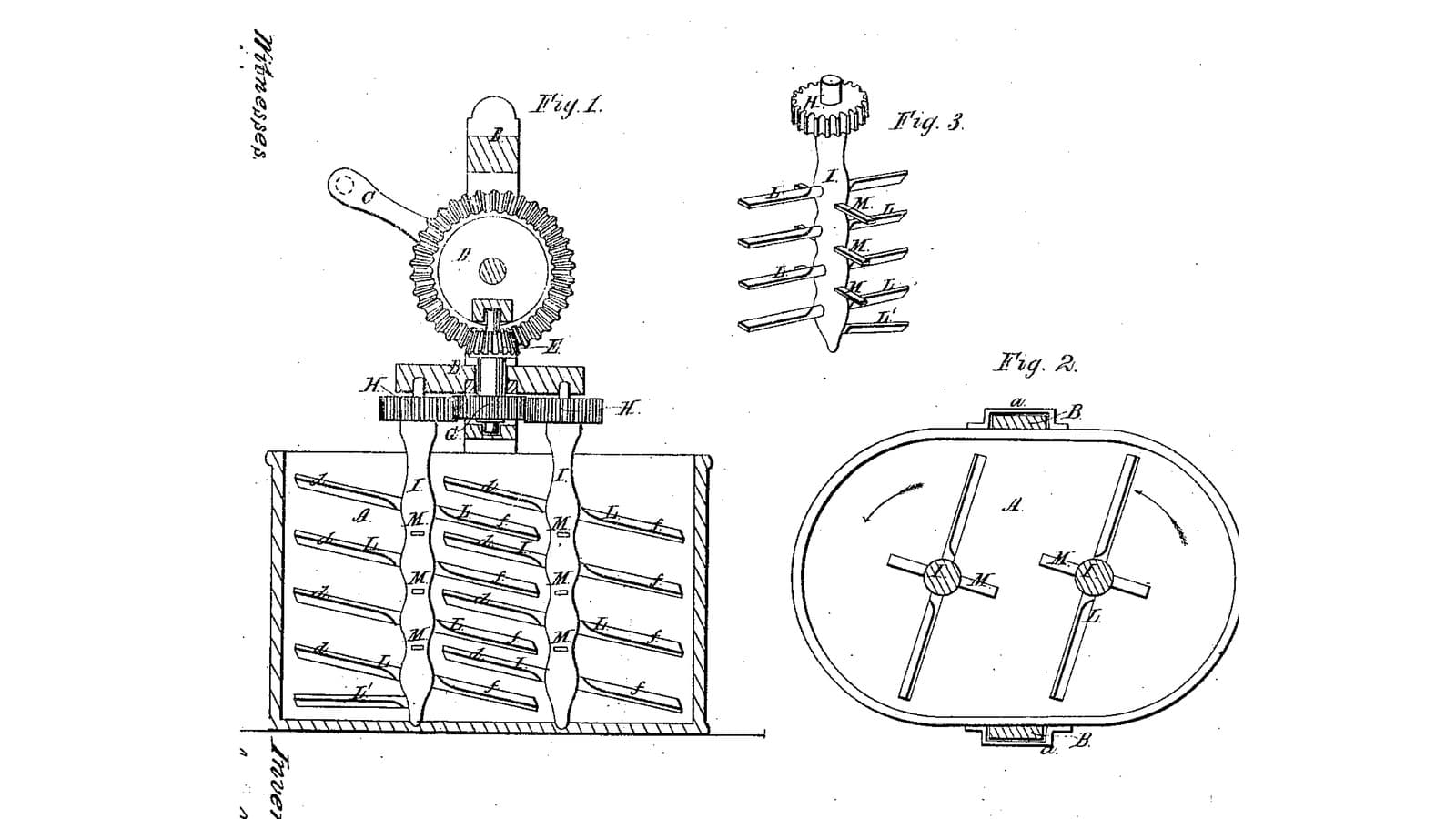
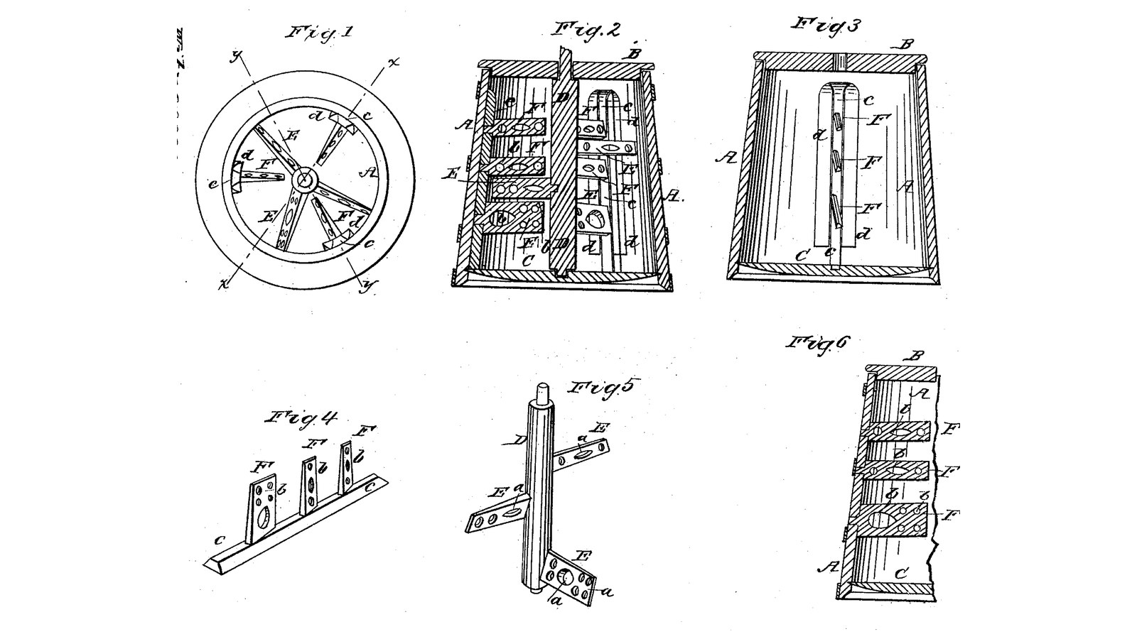
John R. Mickey of Waterford, Pennsylvania, received US 31,554, dated 26 February 1861, for a churn meant to churn sweet milk quickly. Perforated paddles on a geared upright shaft slope one way and pass between perforated paddles fixed round the tub that slope the other way, so the turning set lifts the milk while the fixed set drives it down, forcing it through the holes. The fixed paddles stand on dovetailed bars that slide out of grooves on the tub's wall for cleaning and for gathering the butter. The patent gives no sizes; every size here is ours.
Intermediate
About 3 days

Instructions

1

Paddles that pass without touching

Loading Jupyter Notebook...
2

Wings sloping opposite ways passing each other, seven months before

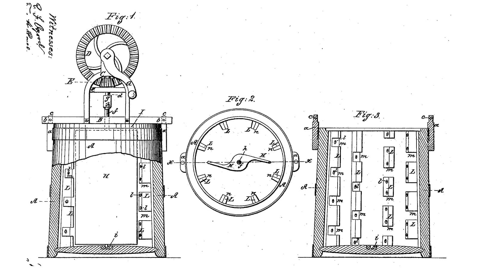
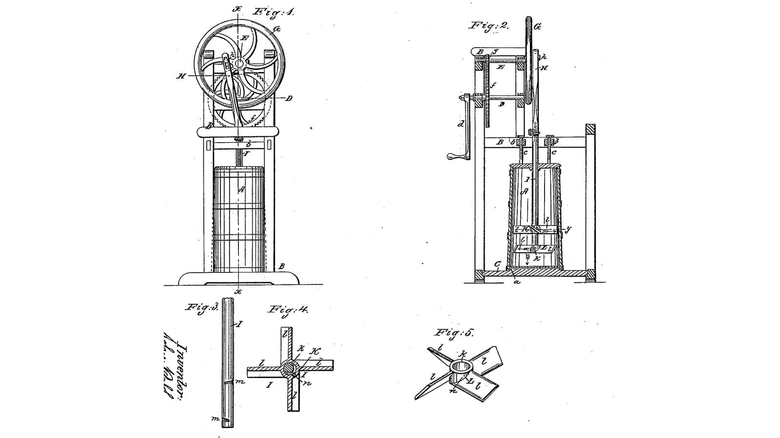
Bissell's two dashers carry wings sloping opposite ways. Mickey fixes one set to the tub and perforates both.
3

Read US 31,554

"The inclination of paddles E. has a tendency to continually elevate the milk while the tendency of paddles F. is opposite and the consequence is that the milk is greatly agitated and so acted upon that the globules are rapidly broken and butter produced in an incredibly short time."
4

Tub A, retaining strips d and slide bars c

Use a 20-litre food-grade bucket as the tub A, with its bottom as C. Plane three hardwood slide bars c 330 mm long to a dovetail section, 20 mm across the inner face, 26 across the back, 11 thick. For each, cut two hardwood strips d 20 mm wide, 300 long, bevelled on one edge to hold the dovetail, and tapered behind to the bucket's wall; screw them to the wall from outside a third of a turn apart, 30 mm above the floor, so the bar slides down between them to rest on the floor. Seal the screw holes.

Materials for this step:

20-Liter Bucket20-Liter Bucket1 piece
Hardwood BoardHardwood Board1 piece
Wood ScrewsWood Screws18 pieces
Silicone SealantSilicone Sealant1 piece

Tools needed:

Table SawTable Saw
RouterRouter
Chisel Set - WoodChisel Set - Wood
Cordless DrillCordless Drill
Drill Bit SetDrill Bit Set
Screwdriver SetScrewdriver Set
Tape MeasureTape Measure
5

Print the lowest fixed paddle F (three)

A fixed paddle F: 60 x 50 x 6 mm with a 12 and a 9 mm hole. Print three. PETG, 0.2 mm layers, 30 % infill, 4 walls.
Design FileSTLCC0 - Free
6

Print the middle fixed paddle F (three)

As the lowest, 42 mm wide. Print three. PETG, 0.2 mm layers, 30 % infill, 4 walls.
Design FileSTLCC0 - Free
7

Print the top fixed paddle F (three)

As the lowest, 34 mm wide. Print three. PETG, 0.2 mm layers, 30 % infill, 4 walls.
Design FileSTLCC0 - Free
8

Fixed paddles F on the bars

Chisel three slots 6 mm wide and 4 deep across the inner face of each bar, at 60, 160 and 260 mm from its foot, sloping 70 degrees from flat, all the same way. Glue the paddles F into them with food-safe silicone and a screw each, widest at the bottom, so they reach in to 70 mm from the tub's centre.

Materials for this step:

PETG FilamentPETG Filament1 piece
Silicone SealantSilicone Sealant1 piece
Wood ScrewsWood Screws9 pieces

Tools needed:

FDM 3D PrinterFDM 3D Printer
Chisel Set - WoodChisel Set - Wood
Cordless DrillCordless Drill
Screwdriver SetScrewdriver Set
9

Print the lowest turning paddle E

A turning paddle E: 101 x 45 x 6 mm with 12, 10 and 8 mm holes. PETG, 0.2 mm layers, 30 % infill, 4 walls.
Design FileSTLCC0 - Free
10

Print the middle turning paddle E

As the lowest, 40 mm wide. PETG, 0.2 mm layers, 30 % infill, 4 walls.
Design FileSTLCC0 - Free
11

Print the top turning paddle E

As the lowest, 35 mm wide. PETG, 0.2 mm layers, 30 % infill, 4 walls.
Design FileSTLCC0 - Free
12

Print the bearing in the bottom C

The bearing on the bucket's floor: 50 mm across, 12 high, with a 16.8 mm hole 8 deep. PETG, 0.2 mm layers, 30 % infill, 4 walls.
Design FileSTLCC0 - Free
13

Shaft D and turning paddles E

Turn a hardwood shaft D 28 mm across and 318 mm long. Set a 10 mm stainless pin 7 mm out of its foot and a 16 mm stainless rod 144 mm long 20 mm into its top. Chisel three slots through it 6 mm wide, sloping 70 degrees from flat the other way from the F paddles, at 98, 198 and 298 mm above its foot, the second a ninth of a turn and the third two ninths round from the first, and glue the paddles E in with silicone and a cross pin, so they reach 115 mm from the centre.

Materials for this step:

Hardwood BoardHardwood Board1 piece
Stainless Steel RodStainless Steel Rod2 pieces
PETG FilamentPETG Filament1 piece
Silicone SealantSilicone Sealant1 piece
Hardwood DowelsHardwood Dowels1 piece

Tools needed:

FDM 3D PrinterFDM 3D Printer
Wood LatheWood Lathe
Chisel Set - WoodChisel Set - Wood
Cordless DrillCordless Drill
Drill Bit SetDrill Bit Set
HacksawHacksaw
14

Print the pinion

The pinion on the shaft's top: 14 teeth, module 2.5, 16.2 mm bore. PETG, 0.2 mm layers, 30 % infill, 4 walls.
Design FileSTLCC0 - Free
15

Print the driving wheel

The driving wheel on the crank shaft: a crown wheel of 42 teeth, module 2.5, 16.2 mm bore. PETG, 0.2 mm layers, 30 % infill, 4 walls.
Design FileSTLCC0 - Free
16

Lid B, cross bar, gearing and crank

Cut a 12 mm HDPE lid B to the bucket's top with a 20 mm hole in the middle. Screw two hardwood ears 30 x 40 mm, 105 long, to opposite sides of the bucket's top, standing 45 mm above its rim. Cut a hardwood cross bar 370 x 140 x 25 mm, notched at its ends to drop over the ears, bored for stainless pins through ears and ends and 16.6 mm at the centre. Screw two hardwood bearing blocks 50 x 25 x 108 mm on it, one 60 to 85 mm in front of the centre and one 25 to 50 behind, bored 16.6 mm across 83 mm up. Stand the shaft on its bearing with the lid and cross bar over it, pin the pinion on its top with its teeth 30 mm above the bar, run a 16 mm stainless crank shaft 180 mm long through the blocks with the driving wheel pinned on meshing the pinion, a shaft collar, and a crank of mild steel flat bar, 100 mm throw, with a hardwood handle.

Materials for this step:

HDPE SheetHDPE Sheet1 piece
Hardwood BoardHardwood Board1 piece
Wood ScrewsWood Screws12 pieces
Stainless Steel RodStainless Steel Rod3 pieces
Shaft CollarShaft Collar1 piece
Split PinSplit Pin4 pieces
Mild Steel Flat BarMild Steel Flat Bar1 piece
Hardwood DowelsHardwood Dowels1 piece
PETG FilamentPETG Filament1 piece

Tools needed:

FDM 3D PrinterFDM 3D Printer
CompassCompass
JigsawJigsaw
Spade Bit SetSpade Bit Set
Table SawTable Saw
Chisel Set - WoodChisel Set - Wood
Cordless DrillCordless Drill
Drill Bit SetDrill Bit Set
HacksawHacksaw
Files (Hand File)Files (Hand File)
Bench ViseBench Vise
Screwdriver SetScrewdriver Set
17

The build in 3D

FreeCAD model of this build, the bucket cut open: three dovetail slide bars in their strips, each with three sloping perforated paddles, the shaft with three paddles sloping the other way, the bearing, lid, cross bar, gears and crank.
Design FileBLENDCC0 - Free
18

Churn and gather

Pour about 14 litres of heavy cream at about 15 °C, checked with the thermometer, into the bucket with the paddles in, put on the lid and drop the cross bar over the ears, pinning it. Turn the crank briskly, timing it. When the butter comes, lift off the gearing and lid, draw the three slide bars up out of their strips, and turn the shaft slowly by hand so the butter gathers on its paddles. Lift it out, take off the butter, pour the buttermilk into a bowl, wash the butter in cold water until it runs clear, salt and weigh it. Before putting the bars back, push them down so any butter lodged in the grooves is forced out at the bottom.

Materials for this step:

Heavy CreamHeavy Cream14 l
Coarse Sea SaltCoarse Sea Salt1 piece
WaterWater1 piece

Tools needed:

Leave-In Probe ThermometerLeave-In Probe Thermometer
StopwatchStopwatch
Digital Kitchen ScaleDigital Kitchen Scale
Stainless Steel Mixing Bowl (Large)Stainless Steel Mixing Bowl (Large)
19

Troubleshooting

Opposed-paddle churn troubleshooting.

Flow

Loading...
20

History and honest limits

**John R. Mickey** of Waterford, Erie County, Pennsylvania, US 31,554, 26 February 1861, "Churn". He claimed "the stationary, perforated paddles F. in combination with the rotating perforated paddles E; when the two sets of paddles (F and E) consist of simple planes, and are arranged obliquely in opposite directions", and disclaimed the tapering solid paddles of John O'Neil's rejected application of 24 June 1852. He made the churn for sweet milk and wrote that "from three gallons of sweet milk three and a quarter pounds of butter" came "in three and a half minutes"; we have not tested that, and we churn cream. He gives the paddles' slope only as "about 70"; we read it from Figs. 2 and 3 as 70 degrees from flat. He left the gearing to "any of the known ways"; ours is a printed crown wheel and pinion. Every size here is ours.

Materials

14

Tools Required

19

Design Files

10

CC0 Public Domain

This blueprint is released under CC0. You are free to copy, modify, distribute, and use this work for any purpose, without asking permission.

Support the Maker by purchasing products through their Blueprint where they earn a Maker Commission set by Vendors, or create a new iteration of this Blueprint and include it as a connection in your own Blueprint to share revenue.

Discussion

(0)

Log in to join the discussion

Loading comments...