Collaboration
ART
BEAUTY & WELLNESS
CRAFT
CULTURE & HISTORY
ENTERTAINMENT
ENVIRONMENT
FOOD & DRINKS
REVERSE ENGINEERING
SCIENCES
SPORTS
TECHNOLOGY
WEARABLES
Interlocked-Blade Dasher Churn: Each Blade's Round Shank Is Bored Through by the Next, So They Key Each Other in the Hub
Buttercup

Created by

Buttercup

11. November 2026IE
0
0
0
0
0

Interlocked-Blade Dasher Churn: Each Blade's Round Shank Is Bored Through by the Next, So They Key Each Other in the Hub

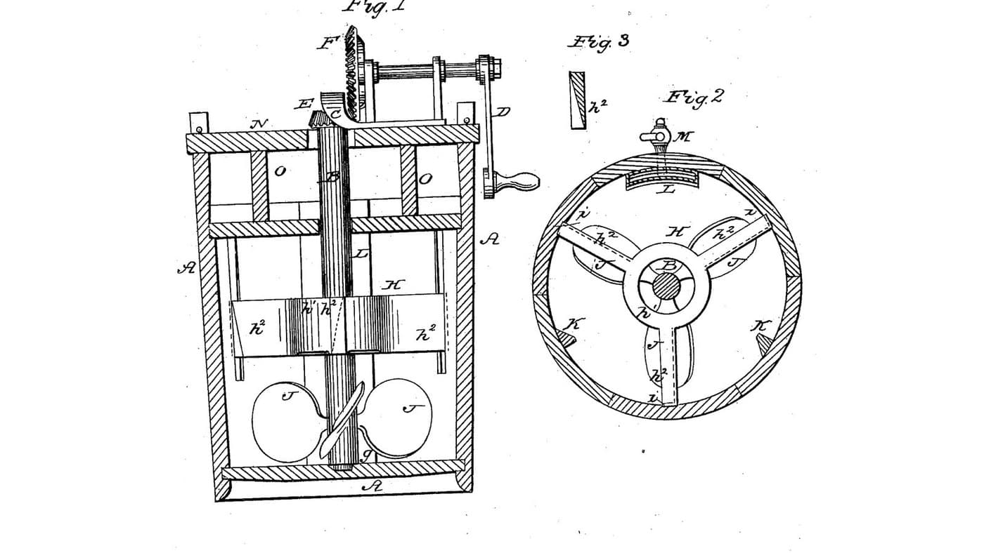
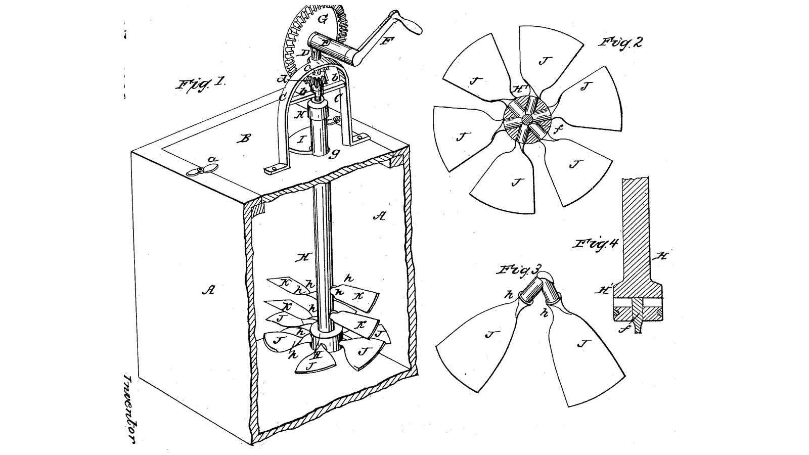
Salem T. Lamb of New Washington, Indiana, received US 30,411, dated 16 October 1860, for fastening the blades of a churn dasher so they never work loose. Each lower blade has a round shank driven into a hole bored to the middle of the hub; boring the next hole cuts the end of the last shank, so every shank keys the one before, and a spindle up the middle locks the set. The dasher turns by a crank and bevel gear on a bracket on the lid, its sloping blades pressing the cream down, and it lifts out through a large opening for cleaning. The patent gives no sizes; every size here is ours.
Intermediate
About 3 days

Instructions

1

Where the shanks lock

Loading Jupyter Notebook...
2

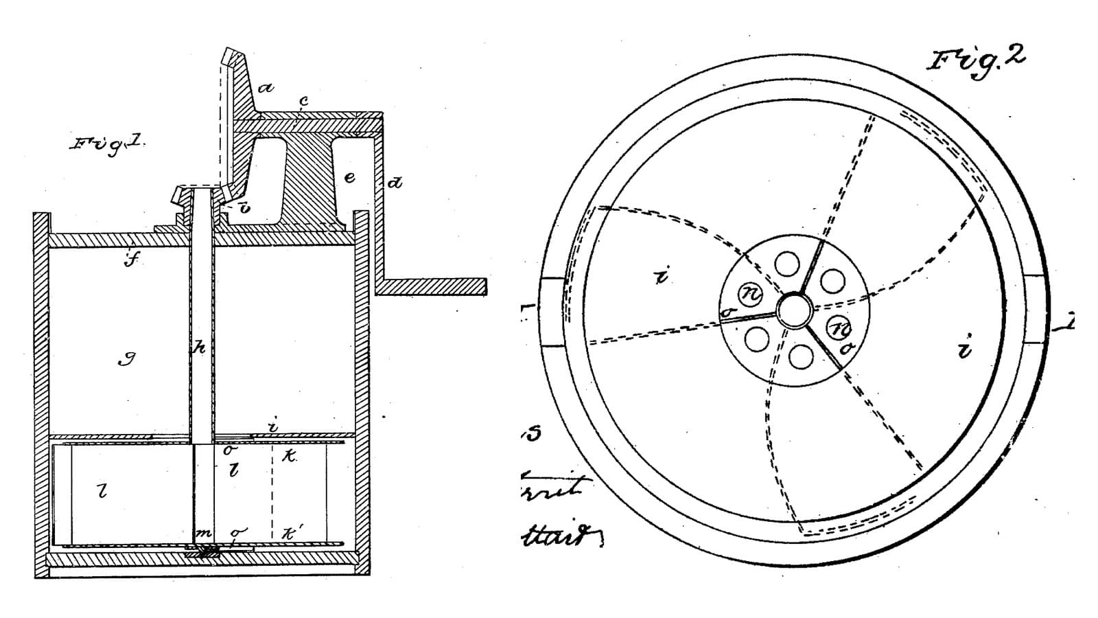
Sloping blades that drive the cream down, six months before

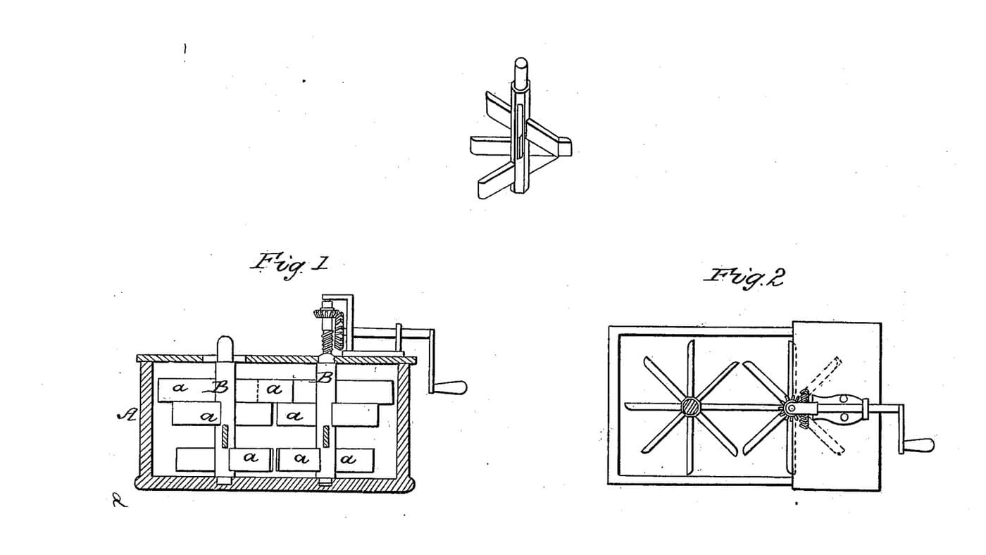
Lynch's propeller dasher also drives the cream down. Lamb's answer is how to keep such blades tight.
3

Read US 30,411

"Another radial hole is then bored for the next adjacent blade, the boring tool passing through or cutting off the end of the first shank. The second blade with the same preparation as the first one is then driven in or united, its shank fitting against and overlapping the first driven one, so as to answer as a key to it, to prevent it from turning or becoming loose."
4

Box A, lid B, cover I and buttons a

Glue up hardwood for a box A 300 x 300 mm inside and 420 deep, sides 22 mm, joints sealed with silicone sealant. Rout a seat round the top for a 22 mm lid B. Cut an opening in the lid 120 mm wide running from 30 mm behind its centre to 140 mm in front; fit a cover I to it with a 22 mm hole at the centre for the shaft c and a slot from that hole to the cover's back edge, so it can be lifted off past the shaft. Turn two hardwood buttons a on screws at the lid's edge to hold it down.

Materials for this step:

Hardwood BoardHardwood Board4 pieces
Wood GlueWood Glue1 piece
Silicone SealantSilicone Sealant1 piece
Wood ScrewsWood Screws24 pieces

Tools needed:

Table SawTable Saw
JigsawJigsaw
RouterRouter
Chisel Set - WoodChisel Set - Wood
Spade Bit SetSpade Bit Set
Cordless DrillCordless Drill
Drill Bit SetDrill Bit Set
Bar ClampBar Clamp
Screwdriver SetScrewdriver Set
Tape MeasureTape Measure
5

Staff H, hub and band

Turn a hardwood staff 40 mm across and 375 mm long, with a hub H 76 mm across for its bottom 80 mm, and the top 15 mm turned to 28 mm for the cap. Turn a groove near the hub's foot and press on a ring cut from a stainless tube as the band, so the hub cannot split when it dries. Bore a 10.2 mm hole up the middle of the hub from below, 50 mm deep, for the spindle f.

Materials for this step:

Hardwood BoardHardwood Board2 pieces
Wood GlueWood Glue1 piece
Stainless Steel TubeStainless Steel Tube1 piece

Tools needed:

Wood LatheWood Lathe
Cordless DrillCordless Drill
Drill Bit SetDrill Bit Set
HacksawHacksaw
Files (Hand File)Files (Hand File)
6

Blades J and K

Carve six lower blades J from hardwood 8 mm thick: 26 mm wide at the neck widening to 100 mm at the tip, reaching 135 mm from the staff's centre, slightly hollowed on top, each on a round shank 20 mm across and 52 mm long, so it reaches the centre, with a small shoulder i, the blade's twist running out along the neck into the shank as the spiral lines h. Carve six upper blades K the same way, 16 to 60 mm wide, reaching 125 mm, on 14 mm shanks 34 mm long.

Materials for this step:

Hardwood BoardHardwood Board1 piece

Tools needed:

Table SawTable Saw
JigsawJigsaw
Wood Carving Gouge SetWood Carving Gouge Set
Chisel Set - WoodChisel Set - Wood
Wood LatheWood Lathe
Files (Hand File)Files (Hand File)
7

Lock the lower shanks

Bore a 20 mm radial hole level into the hub, 40 mm above its foot, to just past the centre. Coat the first J shank near its shoulder with food-safe silicone sealant (the patent used white lead or other cement) and drive it in with the blade sloped 30 degrees. Bore the next hole 60 degrees round, cutting off the end of the first shank, and drive the next blade so its shank overlaps the first. Go on round all six, each keying the last, every blade sloped the same way. Drive a 10 mm stainless rod 60 mm long up the centre hole through the shanks as the spindle f, leaving 14 mm below the hub.

Materials for this step:

Silicone SealantSilicone Sealant1 piece
Stainless Steel RodStainless Steel Rod1 piece

Tools needed:

Cordless DrillCordless Drill
Spade Bit SetSpade Bit Set
Drill Bit SetDrill Bit Set
HacksawHacksaw
8

Set the upper blades

Bore three 14 mm radial holes 120 degrees apart into the staff 180 mm above the hub's foot and three more 210 mm up, turned 60 degrees, so the upper blades break spaces with each other and with the lower. Set the K blades in them with sealant, sloped the same way as the J blades.

Materials for this step:

Silicone SealantSilicone Sealant1 piece

Tools needed:

Cordless DrillCordless Drill
Spade Bit SetSpade Bit Set
9

Print the step

The step on the box's bottom: 60 mm across, 15 high, with a 10.6 mm hole 9 deep for the spindle f. PETG, 0.2 mm layers, 30 % infill, 4 walls.
Design FileSTLCC0 - Free
10

Print the staff cap

The cap glued on the staff's top: 40 mm across, 30 high, a 28 mm socket 15 deep below and a 12.2 mm square socket above for the foot of shaft c. PETG, 0.2 mm layers, 30 % infill, 4 walls.
Design FileSTLCC0 - Free
11

Print the crown wheel G

The driving wheel G on the crank shaft: a crown wheel of 42 teeth, module 2.5, 16.2 mm bore. PETG, 0.2 mm layers, 30 % infill, 4 walls.
Design FileSTLCC0 - Free
12

Print the pinion d

The pinion d on shaft c: 14 teeth, module 2.5, 16.2 mm bore. PETG, 0.2 mm layers, 30 % infill, 4 walls.
Design FileSTLCC0 - Free
13

Bracket C, shaft c, gears and crank F

Screw two hardwood posts 40 x 40 mm, 200 mm tall, to the lid either side of the opening, 160 mm apart over their inside faces; join them with a cross brace b 60 mm up and a top bar at the top, both bored 16.6 mm over the staff. Cut a 16 mm stainless shaft c 283 mm long, file its foot 12 mm square for 14 mm, and run it down through the bar and brace with the pinion d pinned on it above the bar. Screw two hardwood blocks 50 x 25 x 100 mm on the bar either side of the pinion as the sleeve E, bored 16.6 mm across 75 mm above the bar; run a 16 mm stainless crank shaft 180 mm long through them with the crown wheel G pinned on it meshing d, a shaft collar, and a crank F of mild steel flat bar, 100 mm throw, with a hardwood handle.

Materials for this step:

Hardwood BoardHardwood Board1 piece
Stainless Steel RodStainless Steel Rod1 piece
Shaft CollarShaft Collar1 piece
Split PinSplit Pin3 pieces
Mild Steel Flat BarMild Steel Flat Bar1 piece
Hardwood DowelsHardwood Dowels1 piece
Wood GlueWood Glue1 piece
Wood ScrewsWood Screws12 pieces
PETG FilamentPETG Filament1 piece

Tools needed:

FDM 3D PrinterFDM 3D Printer
Table SawTable Saw
Cordless DrillCordless Drill
Drill Bit SetDrill Bit Set
HacksawHacksaw
Files (Hand File)Files (Hand File)
Bench ViseBench Vise
Bar ClampBar Clamp
Screwdriver SetScrewdriver Set
14

The build in 3D

FreeCAD model of this build, the box cut open: the step, the staff with its banded hub, the six lower blades on interlocked shanks and the six upper blades, the lid with its opening and cover, and the bracket with shaft c, pinion, crown wheel and crank.
Design FileBLENDCC0 - Free
15

Churn, gather and lift out

Pour about 20 litres of heavy cream at about 15 °C, checked with the thermometer, into the box. Tilt the dasher in through the opening, set its spindle in the step, swing the staff upright under shaft c so the square enters the cap, and put on the cover and lid. Turn the crank briskly so the blades press the cream down, timing it. When the butter comes, turn on the same way but much slower, so the blades roll it into masses. Take off the cover, lift the dasher slowly while turning it backwards by hand so it slips out through the butter. Gather the butter, pour the buttermilk into a bowl, wash the butter in cold water until it runs clear, salt and weigh it. Scald, wash and air-dry the dasher.

Materials for this step:

Heavy CreamHeavy Cream20 l
Coarse Sea SaltCoarse Sea Salt1 piece
WaterWater1 piece

Tools needed:

Leave-In Probe ThermometerLeave-In Probe Thermometer
StopwatchStopwatch
Digital Kitchen ScaleDigital Kitchen Scale
Stainless Steel Mixing Bowl (Large)Stainless Steel Mixing Bowl (Large)
16

Troubleshooting

Interlocked-blade churn troubleshooting.

Flow

Loading...
17

History and honest limits

**Salem T. Lamb** of New Washington, Clark County, Indiana, US 30,411, 16 October 1860, "Fastening Blades of Churn-Dashers". He claimed the "interlocking or overlapping of the shanks of the blades J, so that they shall serve to hold each other firmly in the staff". He set the shanks in white lead or other cement; we use food-safe silicone, as white lead is a lead compound. His hub band was molten metal run into a groove and his gears a cast bracket with bevel wheels; ours are a pressed stainless ring, wooden posts and printed crown gears. The patent gives no sizes; every size here is ours.

Materials

14

Tools Required

20

Design Files

5

CC0 Public Domain

This blueprint is released under CC0. You are free to copy, modify, distribute, and use this work for any purpose, without asking permission.

Support the Maker by purchasing products through their Blueprint where they earn a Maker Commission set by Vendors, or create a new iteration of this Blueprint and include it as a connection in your own Blueprint to share revenue.

Discussion

(0)

Log in to join the discussion

Loading comments...