ART
BEAUTY & WELLNESS
CRAFT
CULTURE & HISTORY
ENTERTAINMENT
ENVIRONMENT
FOOD & DRINKS
REVERSE ENGINEERING
SCIENCES
SPORTS
TECHNOLOGY
WEARABLES
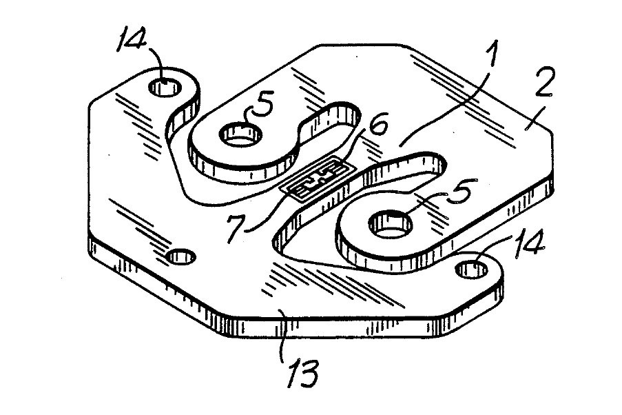


Load Cell: Flat One-Piece Stamping with a U-Shaped Loading Element (Angel, 1991)
A load cell cut in one piece from flat metal, cheap enough to put four in every scale and thin enough to hide in a low floor scale. A beam in the middle carries two strain gauges; a U-shaped arm round it takes the load; a second U-shaped arm holds it down.
Result: a flat load cell whose beam bends into an S under load, stretching one gauge and squeezing the other. It stays accurate when the load is off-centre.
Source: S. Angel, US Patent 4,993,506 (1991). Unknown: the metal, its thickness and all sizes. Ours: bonded wire strain gauges and epoxy. Picture: patent drawing (Fig. 3).
Advanced
1 day
Instructions
1
1
Stamp the cell from thin metal
Stamp the cell from thin metal
Stamp the cell in one piece from thin flat metal. A flexure beam runs down the middle, narrowed at its centre. A U-shaped loading element joins one end of the beam; its two arms reach past the beam's mid-point, each with a hole, and the two holes face each other across the beam's centre. A U-shaped mounting element joins the other end, outside the loading element, with screw holes on a line through the beam's centre. Set the beam's ends by a change in width, not thickness. Not given: the metal, its thickness and the sizes.
Materials for this step:
 Unknown Metal1 thin flat stock
Tools needed:
 Stamping Press
 Unknown Dimensions
2
2
Bond the two strain gauges
Bond the two strain gauges
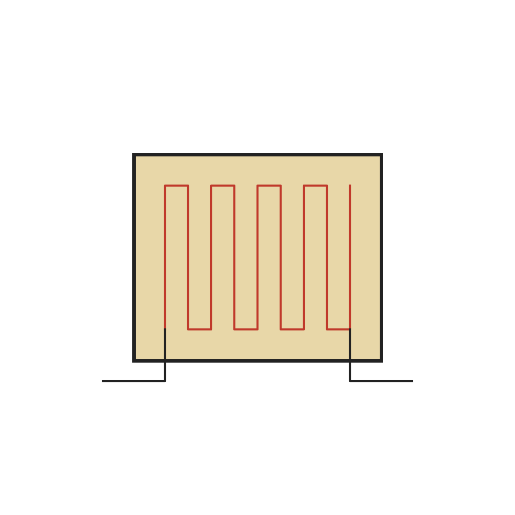
Bond two strain gauges side by side on one face of the narrow middle of the beam. Put their centres at equal distances either side of the beam's centre, and at equal distances from its two edges. Under load the beam bends into an S: one gauge is stretched and rises in resistance, the other is squeezed and falls by the same amount. Wire them as one half of a Wheatstone bridge. The patent allows strain gauges, thick-film resistors or semiconductor sensors. Ours: bonded wire gauges set in epoxy.
Materials for this step:
 Bonded Wire Strain Gauge2 pieces
 Two-Part Epoxy Adhesive (Quick Set)1 a little
 Hookup Wire1 short leads
 Solder Wire1 a little
Tools needed:
 Soldering Iron
3
3
Mount and check
Mount and check
Screw the mounting element down onto small flat raised pads on a rigid plate, so the rest of the cell hangs free to bend. Press on the two loading holes: the half-bridge gives a signal in step with the load. Because the gauges sit symmetrically, the reading holds even when the two arms carry unequal shares, as long as their total is the same. Ours: check the gauges with a meter.
Tools needed:
 Multimeter
Materials
5- 1 thin flat stockPlaceholder
- 2 piecesPlaceholder
- 1 a littlePlaceholder
- 1 short leadsPlaceholder
- 1 a littlePlaceholder
Tools Required
4- Placeholder
- Placeholder
- 2 vendors sell this, none ship to you yetPlaceholder
- Placeholder
Connected Blueprint Materials
This blueprint makes

CC0 Public Domain
This blueprint is released under CC0. You are free to copy, modify, distribute, and use this work for any purpose, without asking permission.
Support the Maker by purchasing products through their Blueprint where they earn a Maker Commission set by Vendors, or create a new iteration of this Blueprint and include it as a connection in your own Blueprint to share revenue.