ART
BEAUTY & WELLNESS
CRAFT
CULTURE & HISTORY
ENTERTAINMENT
ENVIRONMENT
FOOD & DRINKS
REVERSE ENGINEERING
SCIENCES
SPORTS
TECHNOLOGY
WEARABLES
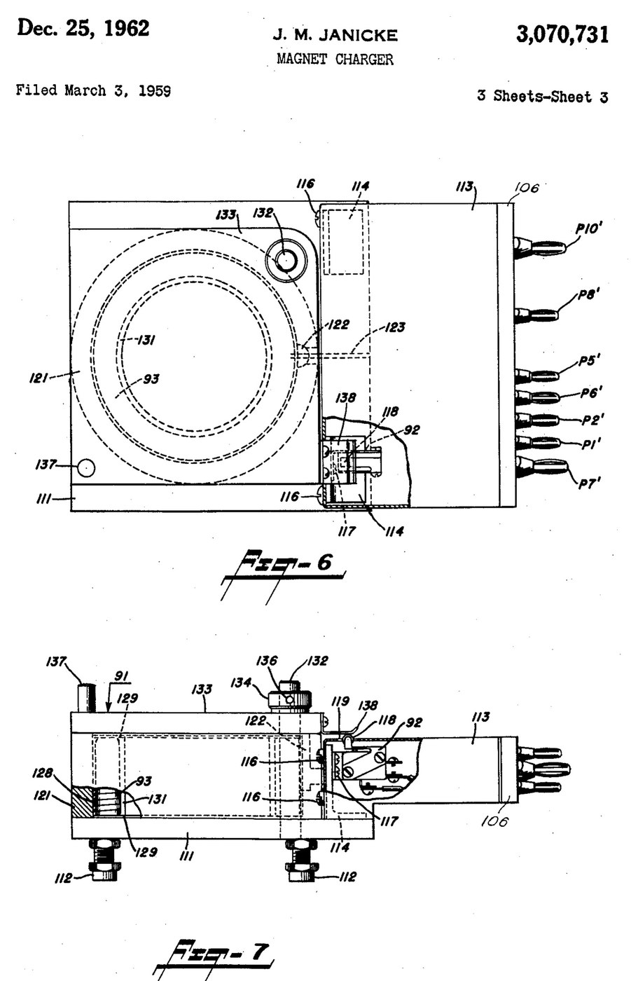


Magnetiser: Capacitor-Discharge Magnet Charger with a Wire-Wound Fixture (Janicke, US 3,070,731, 1962)
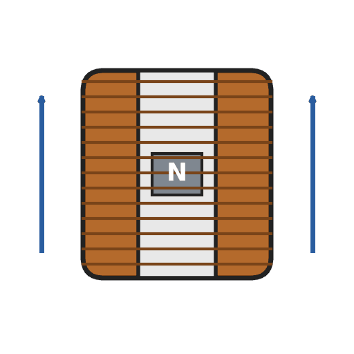
An impulse magnetiser. A capacitor is charged to a high voltage, then an ignitron dumps it all at once through a coil. The magnet sits inside the coil in a closed steel pot, so almost all of the flux goes through it.
Result: a magnet charger that magnetises rods, bars and blocks in one pulse, with an interlocked lid.
Source: J. M. Janicke, US 3,070,731 (1962). Unknown: voltages, capacitance, coil windings, field strength and sizes. Picture: the patent drawing.
Expert
Unknown
Instructions
1
1
Build the charging supply
Build the charging supply
Feed a line switch from the mains through two fuses, with a pilot lamp. Wire a high-voltage transformer with two primaries, which a high-low switch puts in series or in parallel. Run its centre-tapped secondary to two mercury-vapour rectifier tubes, "or the like", with their own filament transformer, so they charge the energy-storage capacitor. A charging on-off switch with a red lamp switches the high-voltage side. A meter with multiplier resistors across the capacitor shows its voltage. Ours: toggle switches, neon lamps, a moving-coil meter. Not given: any voltage or value.
Materials for this step:
 High-Voltage Transformer1 high-voltage transformer
 Mercury-Vapour Rectifier Tube2 rectifier tubes
 Step-Down Transformer1 filament transformer
 Energy-Storage Capacitor1 storage capacitor
 Moving-Coil Panel Meter1 voltage meter
 Unknown Resistor2 meter multipliers
 Toggle Switch3 line, charging and high-low switches
 Fuse2 fuses
 Neon Indicator Lamp2 pilot and red lamps
Tools needed:
 Soldering Iron
 Wire Strippers
2
2
Add the delay and the bleeder
Add the delay and the bleeder
Put a thermal time-delay relay before the charging switch: about thirty seconds after switch-on it energises a control relay, which feeds the charging switch and holds itself on. A third contact of the control relay lifts a bleeder resistor off the capacitor while the charger runs. When the charger is shut down the relay drops out and the bleeder drains the dangerous high-voltage charge from the capacitor.
Materials for this step:
 Time Delay Relay1 thermal delay relay
 Relay1 control relay, three contact setsUnknown Resistor1 bleeder resistor
Tools needed:
Soldering IronWire Strippers3
3
Fit the ignitron firing circuit
Fit the ignitron firing circuit
Put an ignitron in the discharge path of the storage capacitor, as its switch. The meter's multiplier resistors also form a divider that charges a small firing capacitor. Pressing the push button discharges the firing capacitor through a small limiting resistor into the ignitron's igniter, and the ignitron conducts. Not given: the firing capacitor's type and value.
Materials for this step:
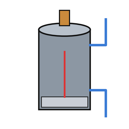 Ignitron1 discharge switch
 Unknown Material1 firing capacitorUnknown Resistor1 limiting resistor
 Push Button1 charge button
Tools needed:
Soldering IronWire Strippers4
4
Build the wire-wound fixture
Build the wire-wound fixture
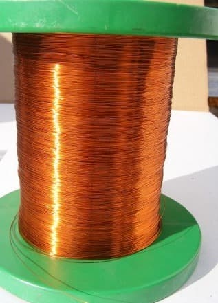
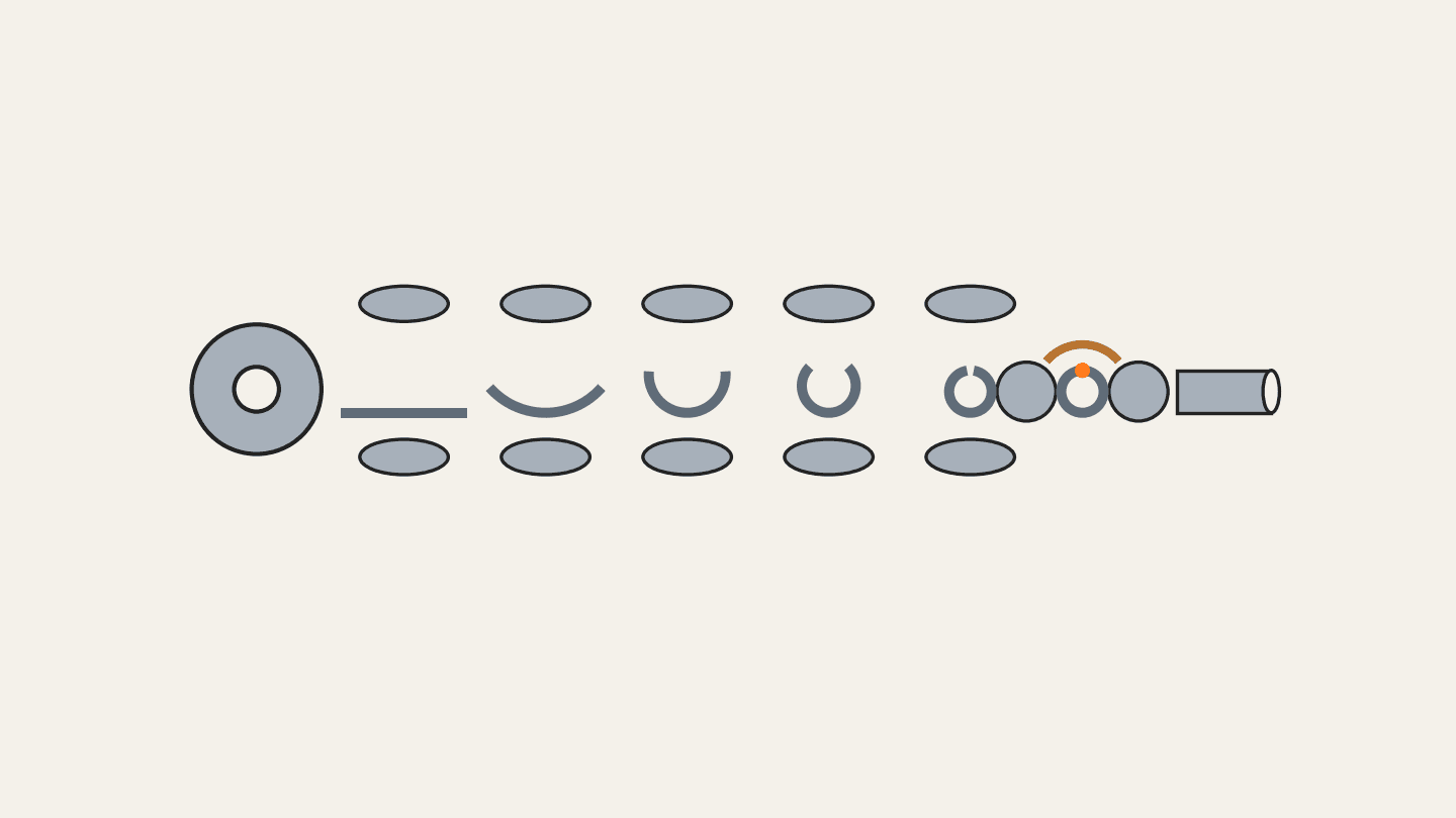
Weld a hollow cylindrical shell onto a base plate on levelling legs, both of magnetic material, to make a pot. Cut slots through the shell and the base plate so they cannot act as a shorted single-turn winding. Set the coil inside the shell in potting compound, with ring-shaped end pieces and a hollow cylindrical core in it. Hinge a square magnetic cover on a post beside the shell, held by a collar and set screw, with a handle. An L-shaped plate on the cover closes a switch in the igniter circuit only when the cover is shut. Wire the coil between the storage capacitor and the ignitron anode. Ours: mild steel, enamelled copper wire, casting epoxy. Not given: sizes, turns.
Materials for this step:
 Mild Steel Plate1 base plate and cover
 Mild Steel Round Tube1 shell
 Enamelled Copper Wire1 coil
 Black Casting Epoxy1 potting compound
 Unknown Metal1 end pieces, core, post, legs
 Microswitch (Lever Actuated)1 lid interlock switch
Tools needed:
 Arc Welder
 Drill Press
 Screwdriver Set
 Unknown Dimensions
5
5
Charge a magnet
Charge a magnet
Put the magnet inside the core. Fill most of the air gap between it and the base plate and cover with soft iron, but leave a small gap near the cover, or the cover will be hard to swing open afterwards. Lay insulating material about 1/16 inch thick on top of the magnet. Close the cover, which arms the igniter switch, charge the capacitor, and press the button: one pulse magnetises it. Ours: wrought iron for the soft iron.
Tools needed:
 Wrought Iron Bar
 Unknown Insulating Material
Materials
20- 1 high-voltage transformerPlaceholder
- 2 rectifier tubesPlaceholder
- 1 filament transformerPlaceholder
- 1 storage capacitorPlaceholder
- 1 voltage meterPlaceholder
- 1 limiting resistorPlaceholder
- Placeholder
- 2 fusesPlaceholder
- 2 pilot and red lampsPlaceholder
- 1 thermal delay relayPlaceholder
- 1 control relay, three contact setsPlaceholder
- 1 discharge switchPlaceholder
- 1 firing capacitorPlaceholder
- Placeholder
- 1 base plate and coverPlaceholder
- 1 shellPlaceholder
- 1 coilPlaceholder
- 1 potting compoundPlaceholder
- 1 end pieces, core, post, legsPlaceholder
- 1 lid interlock switchPlaceholder
Tools Required
8- 2 vendors sell this, none ship to you yetPlaceholder
- Placeholder
- Placeholder
- Placeholder
- Placeholder
- Placeholder
- Placeholder
- Placeholder
Connected Blueprint Materials


This blueprint makes
CC0 Public Domain
This blueprint is released under CC0. You are free to copy, modify, distribute, and use this work for any purpose, without asking permission.
Support the Maker by purchasing products through their Blueprint where they earn a Maker Commission set by Vendors, or create a new iteration of this Blueprint and include it as a connection in your own Blueprint to share revenue.