Collaboration
ART
BEAUTY & WELLNESS
CRAFT
CULTURE & HISTORY
ENTERTAINMENT
ENVIRONMENT
FOOD & DRINKS
REVERSE ENGINEERING
SCIENCES
SPORTS
TECHNOLOGY
WEARABLES
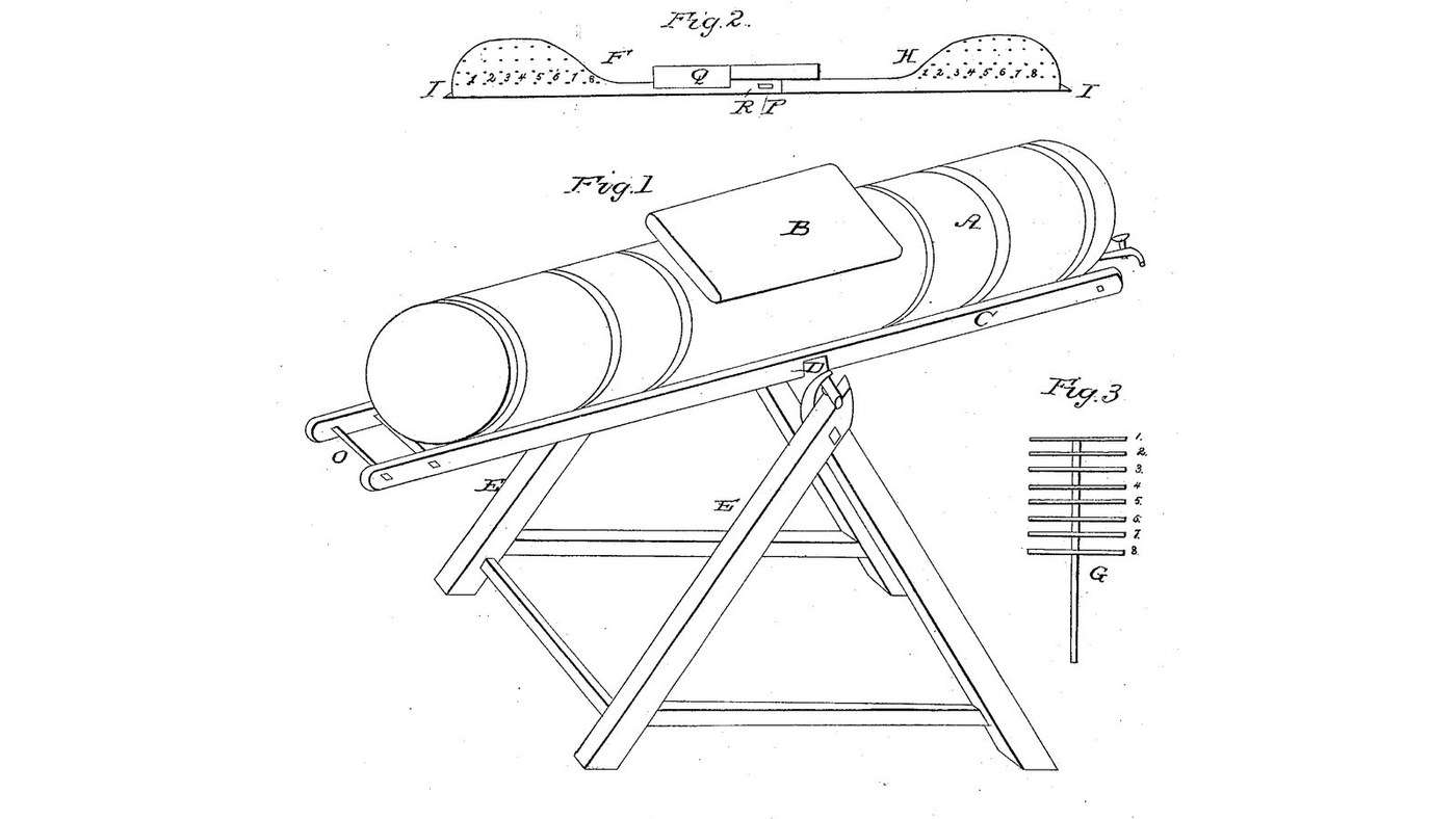

Rocking Barrel Brake-Pin Churn: Cream Rushes End to End Through Rows of Pins, a Diagonal Board Gathers the Butter
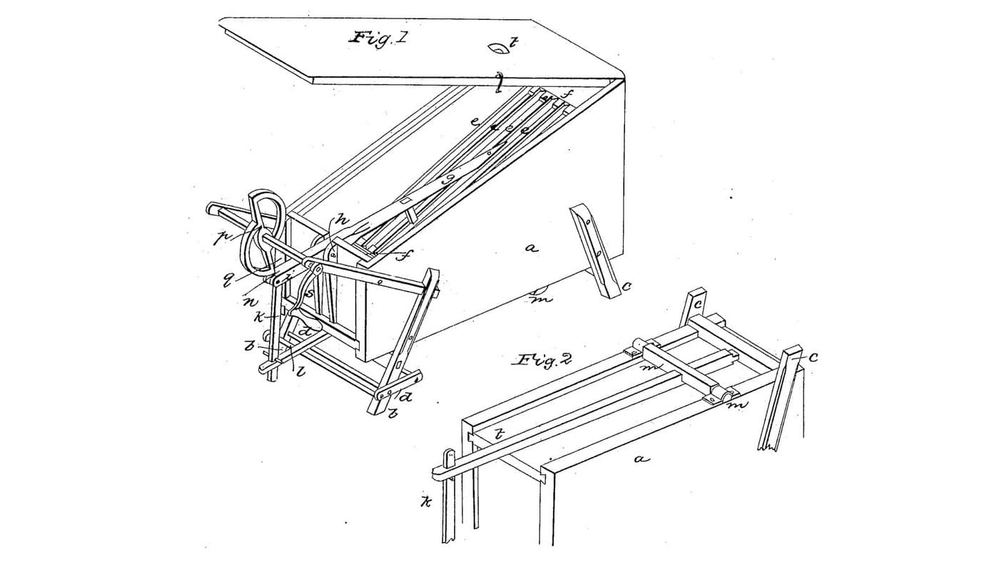
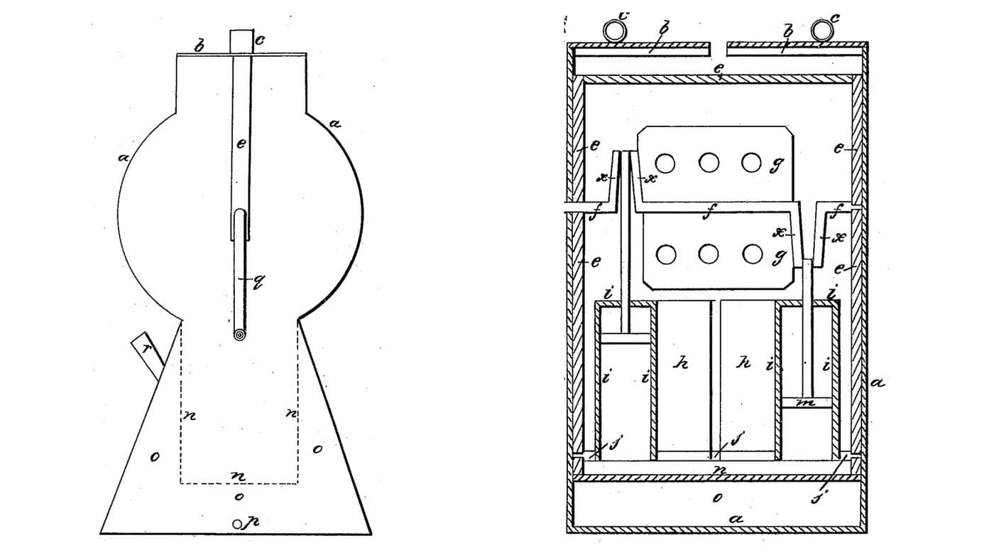
David Newbrough of Clarksburg, Indiana, received US 27,377, dated 6 March 1860, for a churn. A long, narrow barrel pivoted on a saw-buck is rocked end over end, forty degrees each way; the cream rushes from end to end through rows of pins on a brake at each end, which break it to butter. Rocked slowly, a diagonal board in the middle gathers the butter.
The patent suggests a barrel about twelve inches across and three or four feet long; all other sizes are ours.
Intermediate
About 2 days
Instructions
1
1
Why a long, narrow barrel
Why a long, narrow barrel
Loading Jupyter Notebook...
2
2
A rocking churn, the year before
A rocking churn, the year before
Gissinger rocks his churns to work their dashers. Newbrough's barrel has no dasher: rocking moves the cream itself.
3
3
A long box churn, one week before
A long box churn, one week before
Cunningham drives strips through still cream. Newbrough holds the pins still and drives the cream through them.
4
4
Read US 27,377
Read US 27,377
"The rationale of this process is—that the gravity of the cream, or milk, causes it to rush violently from one end of the barrel to the other, and thus—as it dashes through the meshes of the brake-pins the butter globules (of the cream) are broken, and the butter liberated in a granular form, and these myriads of granules are afterward aggregated in a solid butter mass by the gatherer."
5
5
Barrel A, spigot and lid B
Barrel A, spigot and lid B
Cut 1030 mm of food-grade PE pipe 315 mm across with a 12 mm wall. Cut two discs to fit inside it from 15 mm HDPE sheet. Screw a stainless screw eye into the middle of each disc's inner face, 15 mm above the bottom, for the brake's points I; bore one disc 35 mm above the bottom for the spigot and fit it. Press the discs into the pipe's ends, screw them through the wall with eight stainless screws each, and seal inside with silicone sealant. Cut an aperture 460 x 200 mm in the top's middle; keep the piece as the lid, screw two HDPE strips 35 mm wide along its long edges so it rests on the pipe, and hold it with two hooks and eyes.
Materials for this step:
 HDPE Pipe1 piece
 HDPE Sheet1 piece
 Screw Eye2 pieces
 PVC Spigot1 piece
 Machine Screws24 pieces
 Nylon Insert Lock Nut8 pieces
 Silicone Sealant1 piece
 Hook and Eye2 pieces
Tools needed:
 Jigsaw
 Hole Saw Kit
 Cordless Drill
 Drill Bit Set
 Files (Hand File)
 Screwdriver Set
 Tape Measure
6
6
Frame C and handle o
Frame C and handle o
Cut two hardwood rails 30 x 60 mm, 1200 mm long, and bolt one along each side of the barrel at its axis height, with stainless machine screws through rail and pipe wall, the heads inside sealed with silicone, lock nuts outside: 45 mm beyond the spigot end, 125 mm beyond the other. Bore both rails 20.5 mm across at their middle for the pivot. Pass a 30 mm hardwood dowel 480 mm long through the rails 25 mm from their long ends as the handle o.
Materials for this step:
 Hardwood Board2 piecesMachine Screws8 piecesNylon Insert Lock Nut8 piecesSilicone Sealant1 piece
 Hardwood Dowels1 piece
 Wood Glue1 piece
Tools needed:
 Table SawCordless DrillDrill Bit Set
 Spade Bit Set
 Adjustable SpannerScrewdriver SetTape Measure
7
7
Saw-buck E and pivot D
Saw-buck E and pivot D
Make two X's from 50 mm hardwood dowel legs 960 mm long, crossing 650 mm above the floor with their feet 840 apart, and stand them 530 mm apart, one beside each rail. Join them near the floor with two hardwood braces 40 x 30 mm, 560 long. Bore each crossing 20.5 mm across. Lift the barrel between the X's and pass a 20 mm stainless pin 150 mm long through each crossing into its rail; secure with split pins.
Materials for this step:
Hardwood Dowels4 piecesHardwood Board1 piece Wood Screws8 piecesWood Glue1 piece
 Stainless Steel Rod1 piece
 Split Pin2 pieces
Tools needed:
 HacksawCordless DrillDrill Bit SetSpade Bit Set
 Bar ClampScrewdriver SetFiles (Hand File)
8
8
Brake frame F and H, key R and gatherer Q
Brake frame F and H, key R and gatherer Q
From 20 mm hardwood cut the brake board in two halves, 984 mm long together, 40 mm high, rising at each end to a hump 190 high over the last 190 mm, with a point I 6 mm long at each end to enter the screw eye. Halve them together 100 mm at the middle, the joint P, and cut a mortise through it for a hardwood key R. In each hump bore eight columns of 6 mm holes, numbered 1 to 8 as in the patent, 20 mm apart from 335 mm out from the middle, in four rows 25, 65, 105 and 145 mm up; drive in 6 mm stainless pins, centred, 145 mm long in the bottom row and 190 in the others. Screw a hardwood gatherer 200 x 100 mm across the board at 45 degrees, 110 mm from the middle. Pass each half in through the aperture, its point into its screw eye, join them at P and drive the key.
Materials for this step:
Hardwood Board1 pieceStainless Steel Rod2 piecesWood Screws4 piecesWood Glue1 pieceTools needed:
Table SawJigsawCordless DrillDrill Bit SetHacksawFiles (Hand File) Bench Vise
 Sandpaper
9
9
The build in 3D
The build in 3D
FreeCAD model of this build, tipped 15 degrees, the barrel cut through the middle: the brake board with its pinned humps F and H, the gatherer Q and key R, the points I in their screw eyes, the rails C with the handle o, and the saw-buck E with the pivot pins D.
10
10
Churn
Churn
Pour in about 15 litres of heavy cream at about 15 °C, checked with the thermometer, and close the lid. Take the handle, lift that end until the barrel is at about forty degrees, then drop it so the other end rises as far, and repeat in quick succession, timing it. When the butter comes, rock very slowly: the patent says the slow rocking "causes eddies around the gatherer in the center". Draw off the buttermilk at the spigot into a bowl, open the lid, lift out the butter, wash it in cold water until it runs clear, salt and weigh it.
Materials for this step:
 Heavy Cream15 l
 Coarse Sea Salt1 piece
 Water1 piece
Tools needed:
 Leave-In Probe Thermometer
 Stopwatch
 Digital Kitchen Scale
 Stainless Steel Mixing Bowl (Large)
11
11
Troubleshooting
Troubleshooting
Rocking barrel churn troubleshooting.
Flow
Loading...
12
12
History and honest limits
History and honest limits
**David Newbrough** of Clarksburg, Decatur County, Indiana, US 27,377, 6 March 1860, "Churn". He claimed the cream receptacle A, brakes F and H, with gatherer Q, and noted that D. F. Hite and John McLaughlin had already made oscillating churns hinged on a frame, with a perforated board across the middle; his brakes stand at the ends instead. The patent suggests the barrel's size; the PE pipe, the pin rows and lengths, and all other sizes are ours.
Materials
17- 1 piecePlaceholder
- 1 piecePlaceholder
- 2 piecesPlaceholder
- 1 piecePlaceholder
- 32 piecesPlaceholder
- 16 piecesPlaceholder
- 2 piecesPlaceholder
- 2 piecesPlaceholder
- 2 piecesPlaceholder
- 4 piecesPlaceholder
- 3 piecesPlaceholder
- 12 piecesPlaceholder
- 2 piecesPlaceholder
- 2 piecesPlaceholder
- 15 lPlaceholder
- 1 piecePlaceholder
- 1 piecePlaceholder
Tools Required
18- 1 vendor sell this, none ship to you yetPlaceholder
- Placeholder
- 1 vendor sell this, none ship to you yetPlaceholder
- Placeholder
- Placeholder
- Placeholder
- 1 vendor sell this, none ship to you yetPlaceholder
- 1 vendor sell this, none ship to you yetPlaceholder
- Placeholder
- Placeholder
- Placeholder
- Placeholder
- Placeholder
- Placeholder
- Placeholder
- Placeholder
- Placeholder
- Placeholder
Design Files
1This blueprint makes


Related Blueprints
These blueprints share knowledge with this one — techniques, materials, or principles that connect them in the learning graph.
Spring-Pole Cam Churn: A Two-Arc Cam Lifts a Hinged Strip Dasher and a Wooden Spring Pole Drives It Down
by Buttercup
Woodworking
0
0
0
0
0
0
Rocking-Churns Water-Jacket Churn: Two Small Churns Rock and Their Dashers Plunge, Wings Turn Above
by Buttercup
Woodworking
0
0
0
0
0
0

Churning Butter from Cream — The 5,000-Year-Old Fat Separation
by TheChef
CRAFT
60
0
0
0
0
0
CC0 Public Domain
This blueprint is released under CC0. You are free to copy, modify, distribute, and use this work for any purpose, without asking permission.
Support the Maker by purchasing products through their Blueprint where they earn a Maker Commission set by Vendors, or create a new iteration of this Blueprint and include it as a connection in your own Blueprint to share revenue.