ART
BEAUTY & WELLNESS
CRAFT
CULTURE & HISTORY
ENTERTAINMENT
ENVIRONMENT
FOOD & DRINKS
REVERSE ENGINEERING
SCIENCES
SPORTS
TECHNOLOGY
WEARABLES
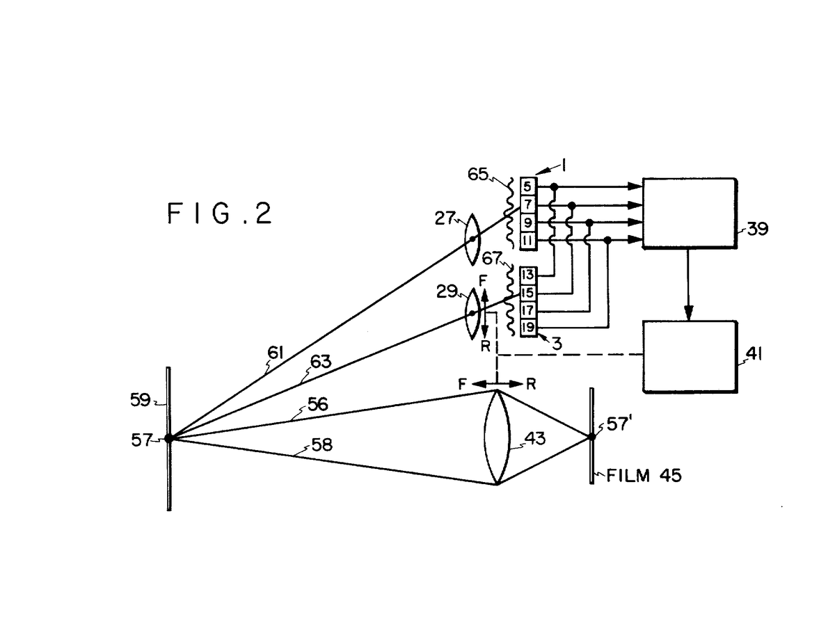

Passive Autofocus (Two-Array Comparison)
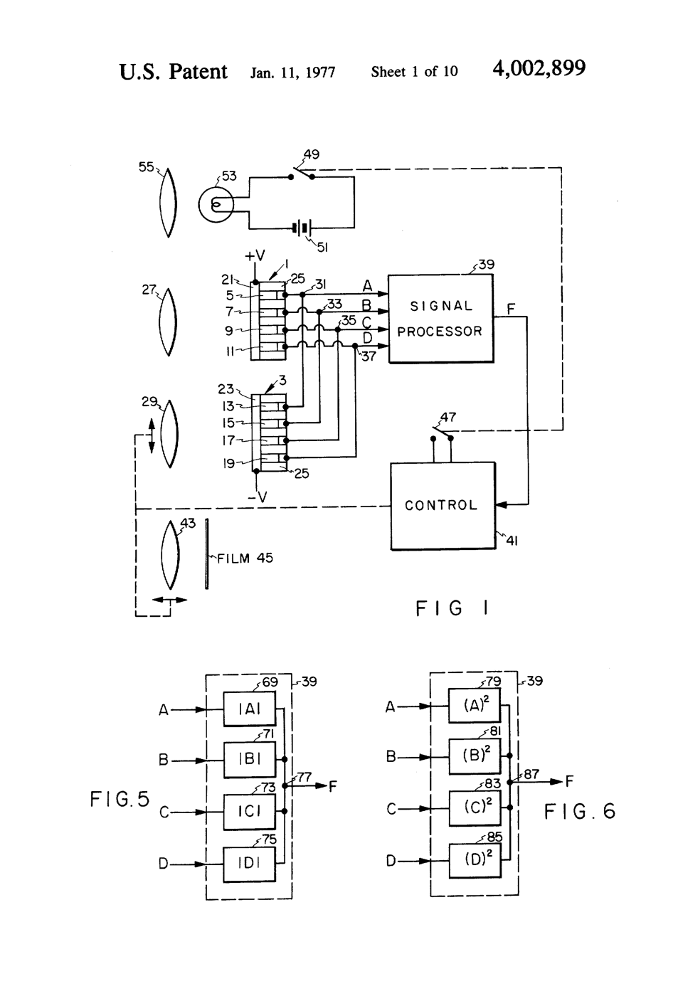
Norman Stauffer at Honeywell built a focus detector from two rows of tiny light sensors side by side on one chip. In his FIGURE 2 each row views the subject through its own small lens, a short distance from the other - like the two windows of a rangefinder. How far one row's picture is shifted against the other's gives the subject's distance, and the camera sets the taking lens to match, without trial and error. Compact cameras from 1977 used it; later SLRs moved the same comparison behind the taking lens itself (phase detection).
**US 4,002,899**, "Focus detecting apparatus", Stauffer, assigned to Honeywell, filed 31. October 1975, granted 11. January 1977: "radiation responsive elements formed on a single planar substrate and divided into two similar coplanar detector arrays lying immediately adjacent each other".
**You see the principle with a card**: a two-hole mask gives a lens two viewpoints, just as Stauffer's two lenses do; out of focus the point splits in two, and which spot vanishes when you cover one hole tells you which way to focus.
Intermediate
90 minutes
Instructions
1
1
Make the two-hole mask
Make the two-hole mask
Cut a card disc to fit a lens holder. Punch two 3 mm holes 20 mm apart, symmetric about the centre.
Materials for this step:
 Black Card Stock1 sheet
Tools needed:
 Craft Knife
 Steel Ruler
2
2
A point of light
A point of light
Cover the torch with foil pierced by one pin-sized hole. Put it 2 m from the bench in a dim room.
Materials for this step:
 Aluminium Foil1 sheet
 Masking Tape1 roll
Tools needed:
 LED Inspection Flashlight
 Tape Measure
3
3
Split and join
Split and join
Mount a 100 mm convex lens with the mask right in front of it, and a tracing-paper screen behind. Slide the screen: two spots merge into one exactly at focus. Measure their separation 5 and 10 mm either side of focus.
Materials for this step:
 Convex Lens Set (Assorted Focal Lengths)1 set
 Pattern Tracing Paper Roll1 sheet
Tools needed:
 Optical Bench & Rail
 Lens Holder SetSteel Ruler
4
4
Which way?
Which way?
With the screen too close, cover the left hole and note which spot disappears. Repeat with the screen too far. The answer flips: that is the direction signal phase detection gives for free.
5
5
Triangles and correlation
Triangles and correlation
Loading Jupyter Notebook...
6
6
History & Context
History & Context
**What the patent specifies:** two similar, adjacent, coplanar arrays of radiation-sensitive elements on one substrate, whose outputs are compared to measure distance or focus. **Modern build (derived):** a Scheiner two-hole mask - two viewpoints and an image shift, made visible.
Christoph Scheiner described the two-hole experiment in 1619 to study the eye's focusing. Honeywell's chips put it into cameras; today's phones put phase-detection pixels directly into the image sensor. Its limits: it needs contrast (a blank wall defeats it) and precise alignment between the detector and the lens.
Materials
5- 1 sheetPlaceholder
- 1 sheetPlaceholder
- 1 rollPlaceholder
- 1 setPlaceholder
- 1 sheetPlaceholder
Tools Required
6- Placeholder
- Placeholder
- Placeholder
- 1 vendor sell this, none ship to you yetPlaceholder
- Placeholder
- Placeholder
Related Blueprints
These blueprints share knowledge with this one — techniques, materials, or principles that connect them in the learning graph.

CC0 Public Domain
This blueprint is released under CC0. You are free to copy, modify, distribute, and use this work for any purpose, without asking permission.
Support the Maker by purchasing products through their Blueprint where they earn a Maker Commission set by Vendors, or create a new iteration of this Blueprint and include it as a connection in your own Blueprint to share revenue.