
Collaboration
ART
BEAUTY & WELLNESS
CRAFT
CULTURE & HISTORY
ENTERTAINMENT
ENVIRONMENT
FOOD & DRINKS
REVERSE ENGINEERING
SCIENCES
SPORTS
TECHNOLOGY
WEARABLES
Swing-Nut Tubing Cutter: Swing the Blade Support Down and the Jaw Slides to the Tube, Up and the Screw Feeds It (Pritchard, 1941)
Forge

Created by

Forge

13. November 2026NO
0
0
0
0
0

Swing-Nut Tubing Cutter: Swing the Blade Support Down and the Jaw Slides to the Tube, Up and the Screw Feeds It (Pritchard, 1941)

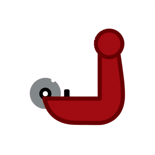
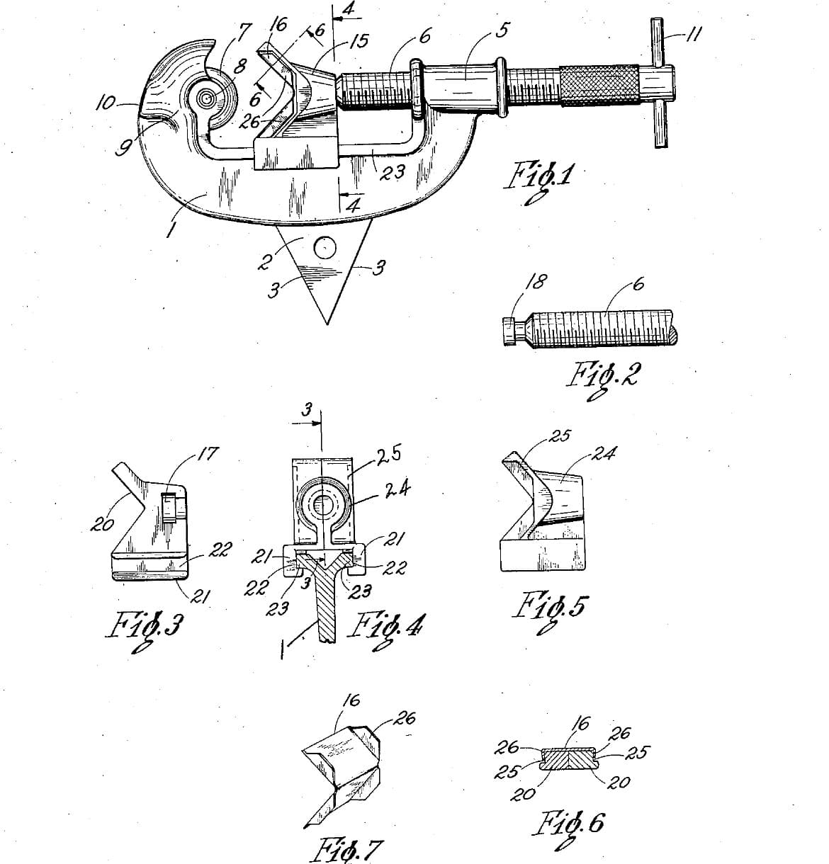
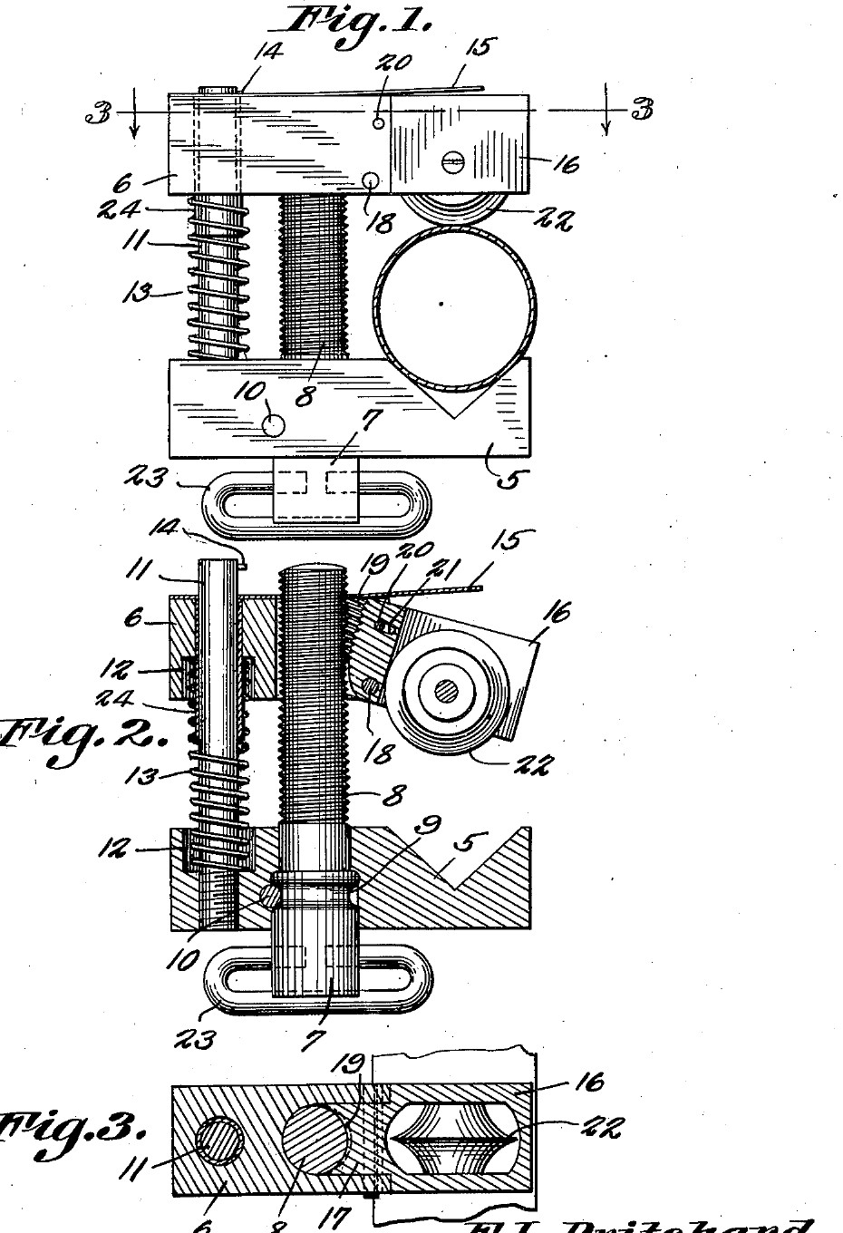
Frank L. Pritchard of Parker, Arizona, received US 2,231,593, dated 11 February 1941, for a tubing cutter small enough for a mechanic's tool box. The tube sits in a V in a fixed jaw. A movable jaw slides on the adjusting screw and a guide pin, with a spring pushing the jaws apart. The cutting wheel is held by a pivoted support with threads on its inner edge. Swung down, the support lets go of the screw, so the jaw can be pushed straight onto any tube. Swung up, it meshes with the screw again and the screw feeds the wheel in. We make his parts from steel bar and plate. All sizes are ours.
Intermediate
About 3 days

Instructions

1

The swing that lets go

Loading Jupyter Notebook...
2

Read US 2,231,593

"The pivoted blade support 16 may swing downwardly until the threads thereof will be free of the threads of the screw 8. The movable jaw 6 may now be slid downwardly until the pivoted blade support is in its proper cutting position."
3

Print the template

Both jaws, the blade support, the wheel and a 15 mm tube at 1:1, with the screw, pin and pivot holes. print at 100 % (check the 50 mm bar).
Design FilePDFCC0 - Free
4

Make the stationary jaw

Saw 64 mm of 16 mm square bar, or of 16 mm plate. File the 90 degree V 8 mm deep in its top face. Drill the 6 mm pin hole and a 10 mm hole for the screw, and counterbore the pin hole 10 mm across, 5 mm deep, for the spring. Drill the 3 mm cross-pin hole across the jaw so it just cuts into the side of the screw hole.

Materials for this step:

Mild Steel PlateMild Steel Plate1 piece

Tools needed:

HacksawHacksaw
File SetFile Set
Drill PressDrill Press
Machine ViceMachine Vice
Drill Bit SetDrill Bit Set
Center PunchCenter Punch
ScriberScriber
Bench ViseBench Vise
Digital Caliper 6-InchDigital Caliper 6-Inch
5

Make the movable jaw and the support

Saw the movable jaw 50 mm long from the same bar. Drill the 6.2 mm pin hole and its spring counterbore. Saw and file a slot 8.2 mm wide down its middle, from 22 mm to the end. Saw the blade support from 14 mm plate to the template. File its upper part down to 8 mm thick, centred, so it slides into the slot, and file away its lower inner corner. Saw a 7 mm slot up its lower part for the wheel. Drill the pivot and stop-pin holes through the jaw and support together, and file the stop-pin hole in the support into a short slot.

Materials for this step:

Mild Steel PlateMild Steel Plate1 piece

Tools needed:

HacksawHacksaw
File SetFile Set
Needle File SetNeedle File Set
Drill PressDrill Press
Machine ViceMachine Vice
Drill Bit SetDrill Bit Set
Bench ViseBench Vise
Digital Caliper 6-InchDigital Caliper 6-Inch
6

Tap the half nut

Pin the support in the jaw, swung up, and clamp it there. Drill 6.8 mm down the screw axis through both, so the drill cuts a shallow groove in the support's inner edge, then tap it M8 through both. Take the support out and open the jaw's own hole to 8.5 mm, so the screw passes freely and only the support's threads hold it.

Tools needed:

Drill PressDrill Press
Machine ViceMachine Vice
Drill Bit SetDrill Bit Set
Tap and Die SetTap and Die Set
Cutting OilCutting Oil
7

Make the screw and the guide pin

Turn the top 62 mm of a 90 mm piece of 10 mm bar to 8 mm and cut an M8 thread on it with the die. Turn a groove 1.5 mm deep and 3.2 mm wide in the plain part, where the cross pin will sit, and drill a 6 mm hole across its bottom end for a T-bar. Cut the guide pin, 80 mm of 6 mm rod, and drill a 3 mm hole across its top for the stop pin.

Materials for this step:

Mild Steel Round BarMild Steel Round Bar1 piece
Mild Steel RodMild Steel Rod1 piece

Tools needed:

Metal LatheMetal Lathe
Lathe Chuck 3-JawLathe Chuck 3-Jaw
Lathe Cutting ToolLathe Cutting Tool
Parting ToolParting Tool
Tap and Die SetTap and Die Set
Drill PressDrill Press
Drill Bit SetDrill Bit Set
HacksawHacksaw
Digital Caliper 6-InchDigital Caliper 6-Inch
8

Turn the cutting wheel

Chuck a tool steel bar and face it. Turn the end to 20 mm across for 10 mm, centre drill and drill a 5 mm hole 10 mm deep, and turn the edge to a 50 degree vee, 25 degrees each side, sharp in the middle of the 6 mm width. Part it off 6 mm long and take the burr off the hole.

Materials for this step:

Tool Steel BarTool Steel Bar1 piece

Tools needed:

Metal LatheMetal Lathe
Lathe Chuck 3-JawLathe Chuck 3-Jaw
Lathe Cutting ToolLathe Cutting Tool
Parting ToolParting Tool
Center Drill SetCenter Drill Set
Drill Bit SetDrill Bit Set
Digital Caliper 6-InchDigital Caliper 6-Inch
Safety GlassesSafety Glasses
9

Harden and temper

Heat the wheel to a cherry red, until a magnet no longer sticks, and quench it in water, moving it about. Rub it bright with a stone, warm it on a piece of steel plate over the fire, and quench again as soon as it turns a light straw colour.

Tools needed:

ForgeForge
Forge TongsForge Tongs
Small MagnetSmall Magnet
Quench BucketQuench Bucket
WaterWater
Sharpening StoneSharpening Stone
Welding GlovesWelding Gloves
Safety GlassesSafety Glasses
10

Assemble

Drive the guide pin into the stationary jaw. Put the screw into its hole from below and drive the cross pin in so it lies in the groove; the screw must still turn. Fit the T-bar. Slip the spring over the guide pin, then the movable jaw over the pin and the screw, and put the stop pin across the top. Fit the wheel in the support on its 5 mm pin, and pin the support into the jaw with its pivot and stop pins. Rivet a 1.5 mm steel strip along the top of the jaw, sticking out past the support as a thumb piece. Oil the threads.

Materials for this step:

Steel Dowel PinSteel Dowel Pin5 pieces
Compression Spring SetCompression Spring Set1 piece
Spring Steel StripSpring Steel Strip1 piece
Steel RivetsSteel Rivets2 pieces
Mild Steel RodMild Steel Rod1 piece

Tools needed:

Ball Peen HammerBall Peen Hammer
Center PunchCenter Punch
Bench ViseBench Vise
Drill PressDrill Press
Drill Bit SetDrill Bit Set
Cutting OilCutting Oil
11

Cut a copper tube

Mark a copper tube and hold it in a vice with soft jaws, or by hand for small tubes. Swing the support down, push the movable jaw down until the wheel touches the tube in the V, swing it up into the screw, and tighten the screw a little. Turn the cutter once round, give the screw about a quarter turn, and go on until the tube parts. The wheel should run in its own groove; the end should be square and not squeezed oval. Clean the inside of the end with a deburring tool.

Materials for this step:

Copper TubeCopper Tube1 piece

Tools needed:

Bench ViseBench Vise

Deburring ToolDeburring Tool
Digital Caliper 6-InchDigital Caliper 6-Inch
12

Troubleshooting

Swing-nut tubing cutter troubleshooting.

Flow

Loading...
13

History and honest limits

**Frank L. Pritchard** of Parker, Arizona, US 2,231,593, dated 11 February 1941, filed 17 November 1939. He claimed "a pivoted blade support mounted on the movable jaw and having threads on the inner edge thereof adapted to engage the threads of said screw". His movable jaw had a bushing for the guide pin and a looped handle on the screw head; ours has a drilled hole and a T-bar. The patent gives no sizes or materials; all of ours are ours.

Materials

9

Tools Required

27

Design Files

1

CC0 Public Domain

This blueprint is released under CC0. You are free to copy, modify, distribute, and use this work for any purpose, without asking permission.

Support the Maker by purchasing products through their Blueprint where they earn a Maker Commission set by Vendors, or create a new iteration of this Blueprint and include it as a connection in your own Blueprint to share revenue.

Discussion

(0)

Log in to join the discussion

Loading comments...