ART
BEAUTY & WELLNESS
CRAFT
CULTURE & HISTORY
ENTERTAINMENT
ENVIRONMENT
FOOD & DRINKS
REVERSE ENGINEERING
SCIENCES
SPORTS
TECHNOLOGY
WEARABLES
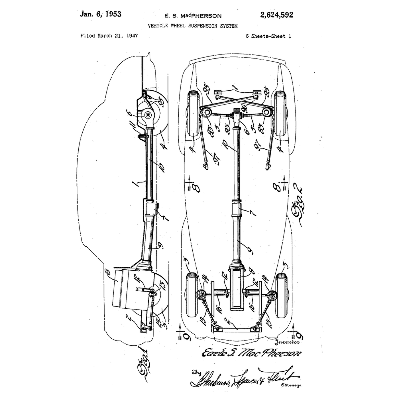

The MacPherson Strut: The Damper Is the Upper Link
Independent front suspension usually needs two wishbones per wheel, a spring and a damper. Earle S. MacPherson, an engineer at General Motors and then Ford, combined the damper, the spring and the upper link into one telescopic strut running from the hub up to the body, with a single lower link at the bottom. His patent was filed in 1947 and granted in 1953.
It is cheap, light and compact, and it leaves room across the car for the engine — which is why most small front-wheel-drive cars use it.
This rung computes how the wheel's camber changes as the suspension moves, and builds a cardboard front-view model to measure it with a protractor.
Intermediate
About 3 hours
Instructions
1
1
Read MacPherson's patent
Read MacPherson's patent
US 2,624,592, 'Vehicle Wheel Suspension System', Earle S. MacPherson of Detroit, filed 21 March 1947 (Serial 736,262), granted 6 January 1953. The wheel's stub axle is connected *"to the body by a vertical telescopic strut"* and *"by a pair of horizontal swinging links"*; one link is *"formed as a turnbuckle"* for adjustment, and rubber bushes give *"a certain degree of universal joint action"*. The figures include a section of the strut's shock-absorber valving.
2
2
Camber change over the travel
Camber change over the travel
Loading Jupyter Notebook...
3
3
Build a front-view model
Build a front-view model
On a sheet of plywood, mark the car's centre line and 'ground'. Use the notebook's dimensions at half scale. Pin a strip of balsa as the lower link at its inner pivot. Make the strut from two cardboard tubes, one sliding in the other, pinned at the top mount and at the link's outer end. Glue a cardboard 'wheel' rigidly to the lower tube.
Move the link end up and down in 20 mm steps and measure the wheel's lean with the protractor. Compare with the notebook. Then move the inner pivot up by 20 mm and repeat: the camber curve changes — this is how suspension designers tune it.
Materials for this step:
 Plywood Sheet1 sheet
 Balsa Wood Sheet1 sheet
 Cardboard Tube2 pieces
 Machine Screws4 pieces
Tools needed:
 Protractor
 Steel Ruler
 Cordless Drill
 Drill Bit Set
4
4
History and context
History and context
**US 2,624,592, 'Vehicle Wheel Suspension System', Earle S. MacPherson; filed 21 March 1947, granted 6 January 1953.** The design first went into production on Ford of Britain cars in the early 1950s and became the most common front suspension on small cars.
**Honest limits.** The camber change and roll behaviour are harder to tune than with two wishbones; the strut's sliding seal carries side loads and wears; and the tall strut sets the height of the bonnet line.
Materials
4- 1 sheetPlaceholder
- 1 sheetPlaceholder
- 2 piecesPlaceholder
- 4 piecesPlaceholder
Tools Required
4- Placeholder
- Placeholder
- 1 vendor sell this, none ship to you yetPlaceholder
- Placeholder
Related Blueprints
These blueprints share knowledge with this one — techniques, materials, or principles that connect them in the learning graph.

The Hydraulic Shock Absorber: Liquid Forced Through a Small Passage
by Emma
Mechanics
31
0
0
0
0
0
Ackermann Steering: The Inner Wheel Turns Further
by Martin
Mechanics
28
0
0
0
0
0
The Leaf Spring: A Beam That Carries the Load and Locates the Axle
by Emma
Mechanics
28
0
0
0
0
0
Constant-Velocity Joint
by Emma
Mechanics
64
0
0
0
0
0
Universal Joint
by Martin
CRAFT
54
0
0
0
0
0
CC0 Public Domain
This blueprint is released under CC0. You are free to copy, modify, distribute, and use this work for any purpose, without asking permission.
Support the Maker by purchasing products through their Blueprint where they earn a Maker Commission set by Vendors, or create a new iteration of this Blueprint and include it as a connection in your own Blueprint to share revenue.