Collaboration
ART
BEAUTY & WELLNESS
CRAFT
CULTURE & HISTORY
ENTERTAINMENT
ENVIRONMENT
FOOD & DRINKS
REVERSE ENGINEERING
SCIENCES
SPORTS
TECHNOLOGY
WEARABLES
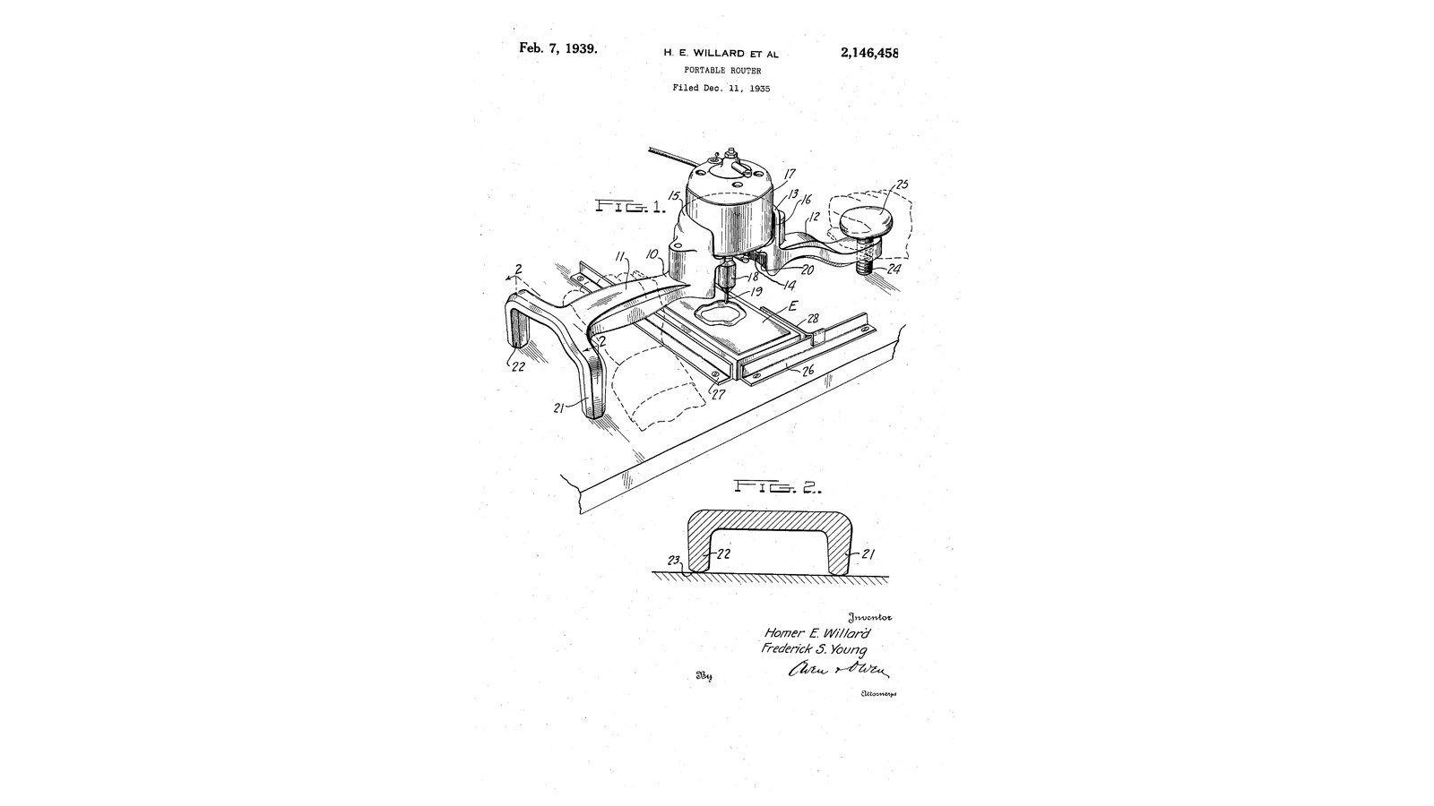


Three-Legged Router: A T-Frame on the Table Beside the Work, Its Depth Set by a Knob While Cutting (Willard & Young, 1939)
Homer E. Willard and Frederick S. Young of Toledo, Ohio, received US 2,146,458, dated 7 February 1939, for a simple portable router with few moving parts. The motor sits in an open-fronted support in the middle of a T-shaped frame, so the bit and the work are always in view. The frame stands on three legs on the table beside the clamped work: two curved legs at one end, and at the other a screw with a knob. Turning the knob with one hand raises or lowers the bit while it cuts.
We print the frame in PETG round a small DC motor. The sizes are ours.
Intermediate
About 1 day
Instructions
1
1
Depth by the knob
Depth by the knob
Loading Jupyter Notebook...
2
2
Read US 2,146,458
Read US 2,146,458
"Thus, by turning the wrist in one direction or the other, the bit 19 may be raised or lowered, as required, without stopping the motor and without removing the hands from the tool."
3
3
Print the frame
Print the frame
The T-shaped frame 10: the motor support 13 with its ledge 14 (an 18 mm hole and two M4 holes 29 mm apart) and curved wall 15, open at the front 16; arm 11 to the cross with two curved legs 21, 22; arm 12 to a boss with an M10 nut trap for the screw leg 24. PETG, 0.2 mm layers, 40 % infill, 5 walls; print it legs up, ledge on the bed.
4
4
Fit the motor
Fit the motor
Print the frame. Fit the collet adapter on the motor's shaft, stand the motor in the support with its face on the ledge and the collet through the hole, and screw it down with two M4 screws. Wire it through a toggle switch to the DC supply as for our 1924 router.
Materials for this step:
 PETG Filament1 piece
 Electric Motor1 piece
 Motor Shaft Collet Adapter1 piece
 Socket Head Cap Screw2 pieces
 Toggle Switch1 piece
 Hook-Up Wire1 piece
 Heat Shrink Tubing1 piece
Tools needed:
 FDM 3D Printer
 DC Power Supply
 Electric Soldering Iron
 Hex Key Set
5
5
The screw leg and knob
The screw leg and knob
Press an M10 nut into the trap under the boss. Cut 100 mm of M10 threaded rod, round its lower end with a file so it slides on the table, and screw it up through the nut. Turn a hardwood knob 25, bore it, and glue it on the rod's top with a nut locked under it.
Materials for this step:
 Hex Nut2 pieces
 Threaded Rod1 piece
 Hardwood Board1 piece
 Wood Glue1 piece
Tools needed:
 Hacksaw
 File Set
 Wood Lathe
 Cordless Drill
 Drill Bit Set
 Adjustable Spanner
6
6
Rout
Rout
Clamp the work down on the table between two strips. Fit a bit and stand the router on the table so its legs are beside the work and the bit is over it. Turn the knob until the bit just clears the work, switch on, and turn it down a little while moving the router over the area to be cut, one hand on arm 11 and the other on the knob.
Tools needed:
 Router Bit SetHardwood Board
 Bar Clamp
 Digital Caliper 6-Inch
 Safety Glasses
7
7
Troubleshooting
Troubleshooting
Three-legged router troubleshooting.
Flow
Loading...
8
8
History and honest limits
History and honest limits
**Homer E. Willard** and **Frederick S. Young** of Toledo, Ohio, US 2,146,458, dated 7 February 1939, filed 11 December 1935. They claimed "a portable router comprising a T-shaped frame having a semi-circular recess in the stem of the T, a bit-operating motor mounted in said recess and a leg projecting in the same direction as the bit from each of the ends of the frame", one leg "screw-threaded through the arm and terminating above the arm in an operating knob". Their work was an electrotype clamped on the table; their motor ran on mains. Ours is a small DC motor in a printed frame. They give no sizes; every size here is ours.
Materials
11- 1 piecePlaceholder
- 1 piecePlaceholder
- 1 piecePlaceholder
- 2 piecesPlaceholder
- Placeholder
- Placeholder
- 1 piecePlaceholder
- 2 piecesPlaceholder
- 1 piecePlaceholder
- 1 piecePlaceholder
- 1 piecePlaceholder
Tools Required
15- Placeholder
- Placeholder
- Placeholder
- Placeholder
- Placeholder
- Placeholder
- Placeholder
- 1 vendor sell this, none ship to you yetPlaceholder
- Placeholder
- Placeholder
- 1 vendor sell this, none ship to you yetPlaceholder
- Placeholder
- Placeholder
- Placeholder
- Placeholder
Design Files
1This blueprint makes

Related Blueprints
These blueprints share knowledge with this one — techniques, materials, or principles that connect them in the learning graph.
CC0 Public Domain
This blueprint is released under CC0. You are free to copy, modify, distribute, and use this work for any purpose, without asking permission.
Support the Maker by purchasing products through their Blueprint where they earn a Maker Commission set by Vendors, or create a new iteration of this Blueprint and include it as a connection in your own Blueprint to share revenue.