Collaboration
ART
BEAUTY & WELLNESS
CRAFT
CULTURE & HISTORY
ENTERTAINMENT
ENVIRONMENT
FOOD & DRINKS
REVERSE ENGINEERING
SCIENCES
SPORTS
TECHNOLOGY
WEARABLES
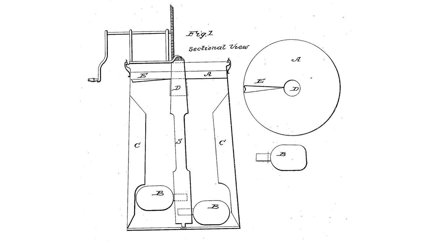

Leaning-Scoop Churn: Three Scoops Tilted 10, 5 and 0 Degrees Throw the Cream at Sharp-Topped Ribs and a Slit Cover
Daniel H. Wiswell of Buffalo, New York, received US 27,504, dated 13 March 1860, for a churn. Three concave scoops on a crank-turned upright shaft lean back by different amounts, 10, 5 and 0 degrees, and throw the cream against ribs on the wall, whose tops slant down to a sharp edge, and up against an inner cover slit on one side with one lip raised over the other.
The patent gives no sizes; every size here is ours, and so is our reading of where the scoops sit.
Intermediate
About 2 days, plus printing
Instructions
1
1
Three scoops, three leans
Three scoops, three leans
Loading Jupyter Notebook...
2
2
An upright churn worked from the top, one month before
An upright churn worked from the top, one month before
Willson strokes his dasher up and down. Wiswell turns his scoops round an upright shaft.
3
3
Read US 27,504
Read US 27,504
"The nature of my invention and improvement consists in the application of the scoops or arms marked B inserted in a shaft marked S, one at the base, the upper edge of which scoop or arm leans backward ten degrees; the second, one third distant to the left, the upper edge of which leans backward five degrees; the third, one third distant from the second and above the other at right angles."
4
4
Print the scoop leaning 10 degrees
Print the scoop leaning 10 degrees
Concave scoop 90 mm long and 64 across, its stem 12 mm, the scoop turned 10 degrees on the stem. PETG, 0.2 mm layers, 40 % infill, 4 walls.
5
5
Print the scoop leaning 5 degrees
Print the scoop leaning 5 degrees
The same scoop turned 5 degrees on its stem. PETG, 0.2 mm layers, 40 % infill, 4 walls.
6
6
Print the upright scoop
Print the upright scoop
The same scoop, upright on its stem. PETG, 0.2 mm layers, 40 % infill, 4 walls.
7
7
Print the crown wheel
Print the crown wheel
Crown wheel, 36 teeth on its face, module 2, with a hub; bored 12.4 mm. PETG, 0.2 mm layers, 40 % infill, 4 walls.
8
8
Print the pinion
Print the pinion
Spur pinion, 12 teeth, module 2, with a hub; bored 12.4 mm. PETG, 0.2 mm layers, 40 % infill, 4 walls.
9
9
Shaft S, spindle box F and scoops B
Shaft S, spindle box F and scoops B
Cut a 35 mm hardwood dowel 348 mm long for the shaft and drill 12 mm stainless spindles 30 mm into each end, the lower one standing out 15 mm, the upper one 70 mm. Screw a hardwood block 60 x 60 x 20 mm to the bucket's floor centre as the spindle box F and bore it 12.6 mm, 15 deep. Bore three 12 mm holes into the shaft for the scoops' stems, a third of a turn apart, 56, 86 and 116 mm above the floor, and glue the scoops in, the 10-degree one lowest, the upright one highest, each leaning back against the way the shaft turns.
Materials for this step:
 20-Liter Bucket1 piece
 Hardwood Dowels1 piece
 Stainless Steel Rod1 piece
 Hardwood Block1 piece
 Wood Glue1 piece
 Wood Screws2 pieces
 Silicone Sealant1 piece
 PETG Filament1 piece
Tools needed:
 FDM 3D Printer
 Hacksaw
 Cordless Drill
 Drill Bit Set
 Files (Hand File)
 Bench Vise
 Protractor
 Screwdriver Set
10
10
Ribs C
Ribs C
Cut four hardwood ribs 20 mm thick and 25 deep, 100 mm long on the inner edge and with their tops slanting down from the wall to the inner edge over 40 mm; plane both faces of the slant to a sharp edge. Screw them inside the bucket a quarter turn apart, 160 mm up from the floor, and seal each screw hole outside with silicone.
Materials for this step:
 Hardwood Board1 pieceWood Screws8 piecesSilicone Sealant1 piece
Tools needed:
 Table Saw
 SandpaperCordless DrillDrill Bit SetScrewdriver Set
11
11
Inner cover A, tube D and slit E
Inner cover A, tube D and slit E
Cut a disc of 3 mm HDPE sheet to fit inside the bucket 300 mm up, with a 40 mm hole in the centre, and fit a printed or hardwood tube D 48 mm across and 60 long in the hole round the shaft. Saw a slit E from the tube to the rim; warm the sheet beside it with the heat gun and lift one side 15 mm so it projects over the other. Screw three small hardwood cleats inside the bucket for the cover to rest on.
Materials for this step:
 HDPE Sheet1 pieceHardwood Board1 pieceWood Screws6 piecesSilicone Sealant1 piece
Tools needed:
 Jigsaw
 Heat GunCordless DrillDrill Bit SetFiles (Hand File)Screwdriver Set
12
12
Bridge and crank
Bridge and crank
Cut a hardwood bridge 350 x 205 x 25 mm to sit on the bucket's rim and bore it 13 mm over the centre for the shaft's upper spindle; fit the pinion on the spindle above it. Screw two hardwood chairs on the bridge carrying a 12 mm stainless crank shaft with the crown wheel meshing the pinion, and fit a hardwood crank with a dowel handle on its outer end; hold it with collars.
Materials for this step:
Hardwood Board2 piecesStainless Steel Rod1 pieceHardwood Dowels1 pieceWood Glue1 pieceWood Screws8 pieces Shaft Collar2 pieces
 Split Pin1 piece
Tools needed:
Table SawCordless DrillDrill Bit Set Spade Bit SetHacksaw
 Bar ClampScrewdriver Set
 Tape Measure
13
13
The build in 3D
The build in 3D
FreeCAD model of this build, the bucket cut through the middle: the shaft S on its spindle box, the three leaning scoops, the ribs, the slit inner cover with its tube, and the bridge with the crank, crown wheel and pinion.
14
14
Churn
Churn
Pour about 6 litres of heavy cream at about 15 °C, checked with the thermometer, into the bucket, set the shaft in its box, lay the cover over the shaft on its cleats, and set the bridge and gearing on the rim. Turn the crank steadily, timing it, so the scoops travel with their hollows forward. When the butter comes, lift off the bridge, cover and shaft, take out the butter, pour the buttermilk into a bowl, wash the butter in cold water until it runs clear, salt and weigh it.
Materials for this step:
 Heavy Cream6 l
 Coarse Sea Salt1 piece
 Water1 piece
Tools needed:
 Leave-In Probe Thermometer
 Stopwatch
 Digital Kitchen Scale
 Stainless Steel Mixing Bowl (Large)
15
15
Troubleshooting
Troubleshooting
Leaning-scoop churn troubleshooting.
Flow
Loading...
16
16
History and honest limits
History and honest limits
**Daniel H. Wiswell** of Buffalo, New York, US 27,504, 13 March 1860, "Churn", assigned to Chas. W. Adams and Debby Pinner. He claimed the inner cover A, the scoops B, and the sharp edge and slant of the ribs' tops, combined. His text does not make plain where each scoop sits; ours are a third of a turn apart, each higher than the last, the third upright. His spindle box is lignum vitae or hemlock knot; ours is hardwood. Every size here is ours.
Materials
15- 1 piecePlaceholder
- 1 piecePlaceholder
- 1 piecePlaceholder
- 1 piecePlaceholder
- 2 piecesPlaceholder
- 24 piecesPlaceholder
- 3 piecesPlaceholder
- 1 piecePlaceholder
- 2 piecesPlaceholder
- 1 piecePlaceholder
- 2 piecesPlaceholder
- 1 piecePlaceholder
- 6 lPlaceholder
- 1 piecePlaceholder
- 1 piecePlaceholder
Tools Required
19- Placeholder
- Placeholder
- 1 vendor sell this, none ship to you yetPlaceholder
- Placeholder
- Placeholder
- Placeholder
- Placeholder
- Placeholder
- 1 vendor sell this, none ship to you yetPlaceholder
- Placeholder
- 1 vendor sell this, none ship to you yetPlaceholder
- 1 vendor sell this, none ship to you yetPlaceholder
- Placeholder
- Placeholder
- 1 vendor sell this, none ship to you yetPlaceholder
- Placeholder
- Placeholder
- Placeholder
- Placeholder
Design Files
6This blueprint makes


Related Blueprints
These blueprints share knowledge with this one — techniques, materials, or principles that connect them in the learning graph.
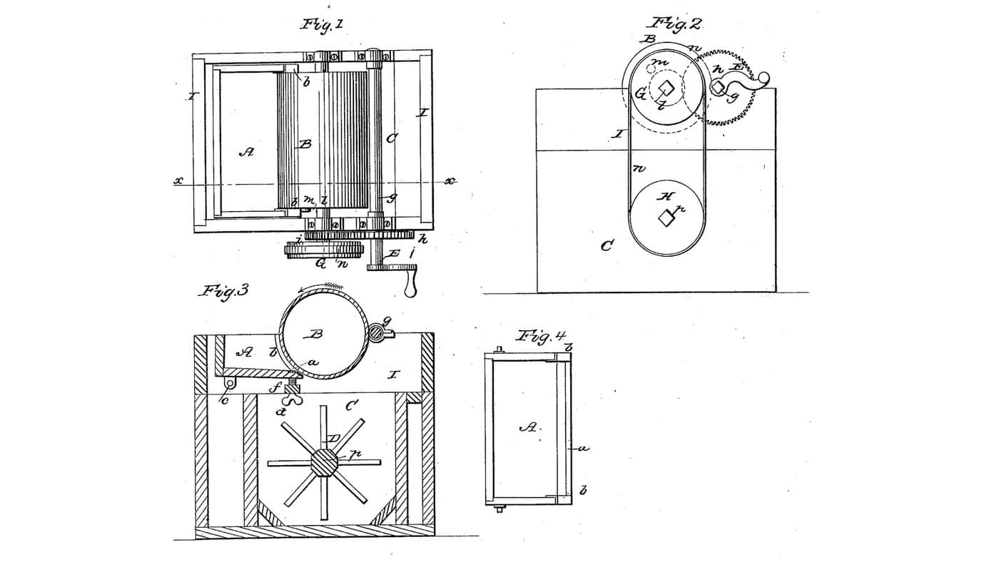
Hot-Water Cylinder Churn: Cream Is Crushed Between a Warm Turning Cylinder and an Adjustable Plate, Then Falls to a Dasher
by Buttercup
Woodworking
0
0
0
0
0
0
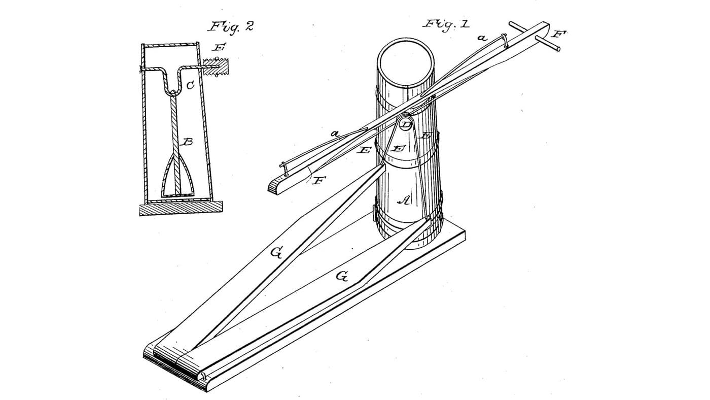
Spring-Bow Churn: A Bow With Two Springs Keeps Its Cord Tight Round a Screw Whirl on the Crank Shaft
by Buttercup
Woodworking
0
0
0
0
0
0

Churning Butter from Cream — The 5,000-Year-Old Fat Separation
by TheChef
CRAFT
60
0
0
0
0
0
CC0 Public Domain
This blueprint is released under CC0. You are free to copy, modify, distribute, and use this work for any purpose, without asking permission.
Support the Maker by purchasing products through their Blueprint where they earn a Maker Commission set by Vendors, or create a new iteration of this Blueprint and include it as a connection in your own Blueprint to share revenue.