Colaboração
ARTE
BELEZA E BEM-ESTAR
ARTESANATO
CULTURA E HISTÓRIA
ENTRETENIMENTO
MEIO AMBIENTE
COMIDA E BEBIDAS
ENGENHARIA REVERSA
CIÊNCIAS
ESPORTES
TECNOLOGIA
TECNOLOGIA VESTÍVEL
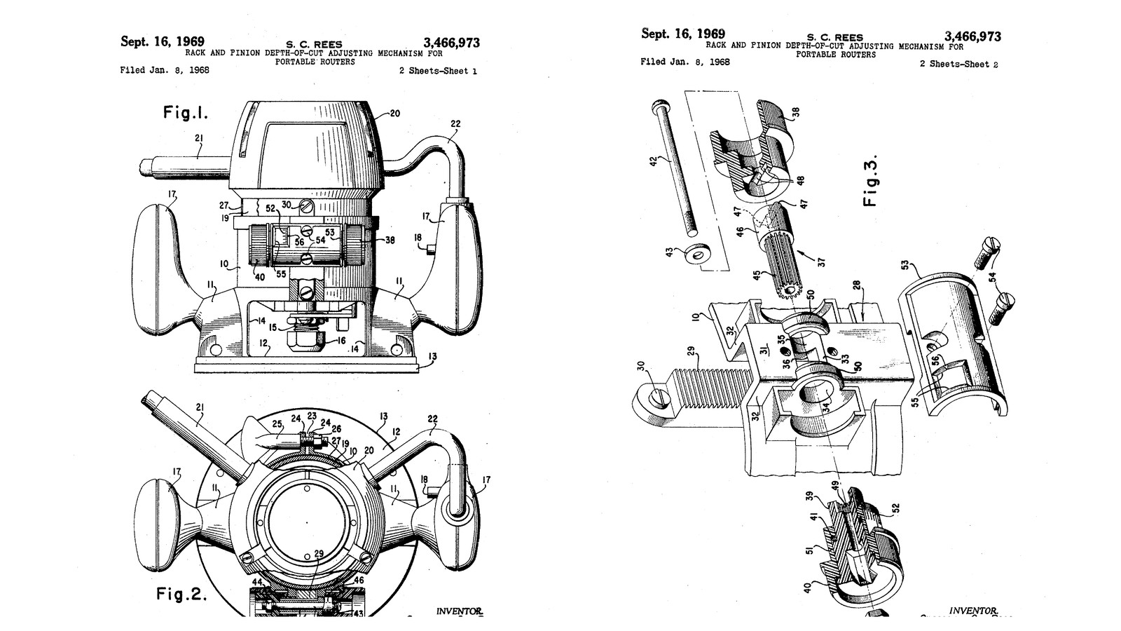

Rack-and-Pinion Router With a Zero-Set Knob: Two Knobs on One Hollow Pinion, Set to Zero on the Work (Rees, 1969)
Spencer C. Rees of Pickens, South Carolina, received US 3,466,973, dated 16 September 1969, for The Singer Company. A rack screwed to the motor housing is moved by a pinion through a window in a box on the base. The pinion is a hollow shaft running in one bore through the box's two side lugs, with a knob at each end. One knob turns it. The other, a zero-set knob with graduations, slips on its sleeve against an O-ring, so it can be set to zero with the bit touching the work. One screw through the middle holds it all together. Only the pinion shaft was metal; the rest was moulded.
We print every part in PETG round a small DC motor. The sizes are ours.
Avançado
About 3 days
Instruções
1
1
What one turn of the knob does
What one turn of the knob does
A carregar o notebook Jupyter…
2
2
Read US 3,466,973
Read US 3,466,973
"The zero-set knob 40 has a reduced diameter portion 51 which carries circumferentially-spaced graduation marks 52 on its surface." "In the above-described structure it will be noted that the only metallic part required is the pinion shaft 37 which is a relatively simple two-diameter piece."
3
3
Print the base
Print the base
The base 10: the split ring with clamp lugs, the box 28 for the rack with its two lugs 50 and stepped bore 33, the window 36, two legs 11 down to the plate 12 with its aperture, and two handle arms. Print it plate down. PETG, 0.2 mm layers, 40 % infill, 5 walls.
4
4
Print the motor housing
Print the motor housing
The housing 19: a tube for a 42 mm motor, 56 mm outside, a ledge with an 18 mm hole and two M4 holes, and two M3 holes for the rack. Print it ledge down. PETG, 0.2 mm layers, 40 % infill, 5 walls.
5
5
Print the small parts
Print the small parts
One plate: the rack 29 (module 1.5), the hollow pinion shaft 37 with its toothed (splined) part, bearing part and end ribs, the adjusting knob 38 with grooves, the flanged sleeve 39, the zero-set knob 40 with 20 graduations and an O-ring groove, and the cover plate 53 with its window 55 and mark 56. PETG, 0.2 mm layers, 40 % infill, 5 walls.
6
6
Motor in the housing
Motor in the housing
Fit the collet adapter on the motor's shaft, stand the motor in the housing on its ledge and screw it down with two M4 screws; wire it through a toggle switch to the DC supply. Screw the rack to the housing's front with two M3 screws.
Materiais para este passo:
 Filamento PETG1 peça
 Motor elétrico1 peça
 Adaptador de pinça para eixo de motor1 peça
 Parafuso de cabeça cilíndrica com sextavado interior2 peças
 Parafusos de máquina2 peças
 Interruptor de alavanca1 peça
 Fio de ligação1 peça
 Manga termorretráctil1 peça
Ferramentas necessárias:
 Impressora 3D de filamento (FDM)
 Fonte de alimentação de corrente contínua
 Ferro de solda elétrico
 Jogo de chaves Allen
 Conjunto de chaves de fendas
 Rebarbador manual
7
7
Base and handles
Base and handles
Turn two hardwood handles 17 and bolt one to each arm with an M8 bolt. Slide the housing into the base with the rack in the box's channel, and put an M5 screw with a wing nut through the clamp lugs.
Materiais para este passo:
 Tábua de madeira de lei1 peça
 Sortido de parafusos sextavados2 peças
 Porca sextavada3 peçasParafuso de cabeça cilíndrica com sextavado interior1 peça
 Porca borboleta1 peça
Ferramentas necessárias:
 Torno de madeira
 Berbequim sem fios
 Jogo de brocas
 Chave inglesa ajustável
8
8
Pinion, knobs and cover
Pinion, knobs and cover
Push the pinion shaft through the box's bore from the right, its toothed part through the window meshing with the rack, its bearing part in the right lug. Fit the O-ring in the zero-set knob's groove, push the sleeve into the knob, and slide them onto the shaft's toothed end from the left, the sleeve in the left lug. Fit the adjusting knob on the right end, its grooves on the shaft's ribs. Pass a long M4 screw through knob, shaft and sleeve with a washer, into a nut in the sleeve, and tighten it until the knobs have only a little end play. Screw the cover over the box with two M3 screws.
Materiais para este passo:
 O-ring1 peçaParafuso de cabeça cilíndrica com sextavado interior1 peça
 Anilha plana1 peçaPorca sextavada1 peçaParafusos de máquina2 peças
Ferramentas necessárias:
Jogo de chaves AllenConjunto de chaves de fendas9
9
Set zero and rout
Set zero and rout
Fit a bit. Loosen the clamp, turn the adjusting knob until the bit's tip touches the work, then turn the zero-set knob alone until its zero lines up with the cover's mark. Turn the adjusting knob to the depth wanted, read off the graduations, and clamp. Rout with both hands on the handles.
Ferramentas necessárias:
 Conjunto de fresas de tupiaTábua de madeira de lei
 Sargento de barra
 Paquímetro digital de 6 polegadas
 Óculos de segurança
10
10
Troubleshooting
Troubleshooting
Rack and pinion router troubleshooting.
Flow
Loading...
11
11
History and honest limits
History and honest limits
**Spencer C. Rees** of Pickens, South Carolina, assignor to The Singer Company, US 3,466,973, dated 16 September 1969, filed 8 January 1968. He claimed a rack on the motor housing, "a pair of lugs formed on the base in fixed spaced relation on opposite sides of the rack and having aligned cylindrical apertures", a hollow pinion shaft, an adjusting knob, a flanged sleeve, "a zero-set knob frictionally coupled to said sleeve", and "single fastening means" through them all. His pinion shaft was metal and the rest moulded; ours is all printed. His motor ran on mains; ours is a small DC motor. He gives no sizes; every size here is ours.
Materiais
14- 1 peçaReferência
- 1 peçaReferência
- Referência
- Referência
- 4 peçasReferência
- Referência
- Referência
- 1 peçaReferência
- 1 peçaReferência
- Referência
- 4 peçasReferência
- 1 peçaReferência
- 1 peçaReferência
- 1 peçaReferência
Ferramentas necessárias
15- Referência
- Referência
- Referência
- Referência
- Referência
- Referência
- 1 vendor sell this, none ship to you yetReferência
- Referência
- Referência
- 1 vendor sell this, none ship to you yetReferência
- Referência
- Referência
- Referência
- Referência
Ficheiros de design
3Este projeto faz

Blueprints relacionados
Estes blueprints compartilham conhecimento — técnicas, materiais ou princípios
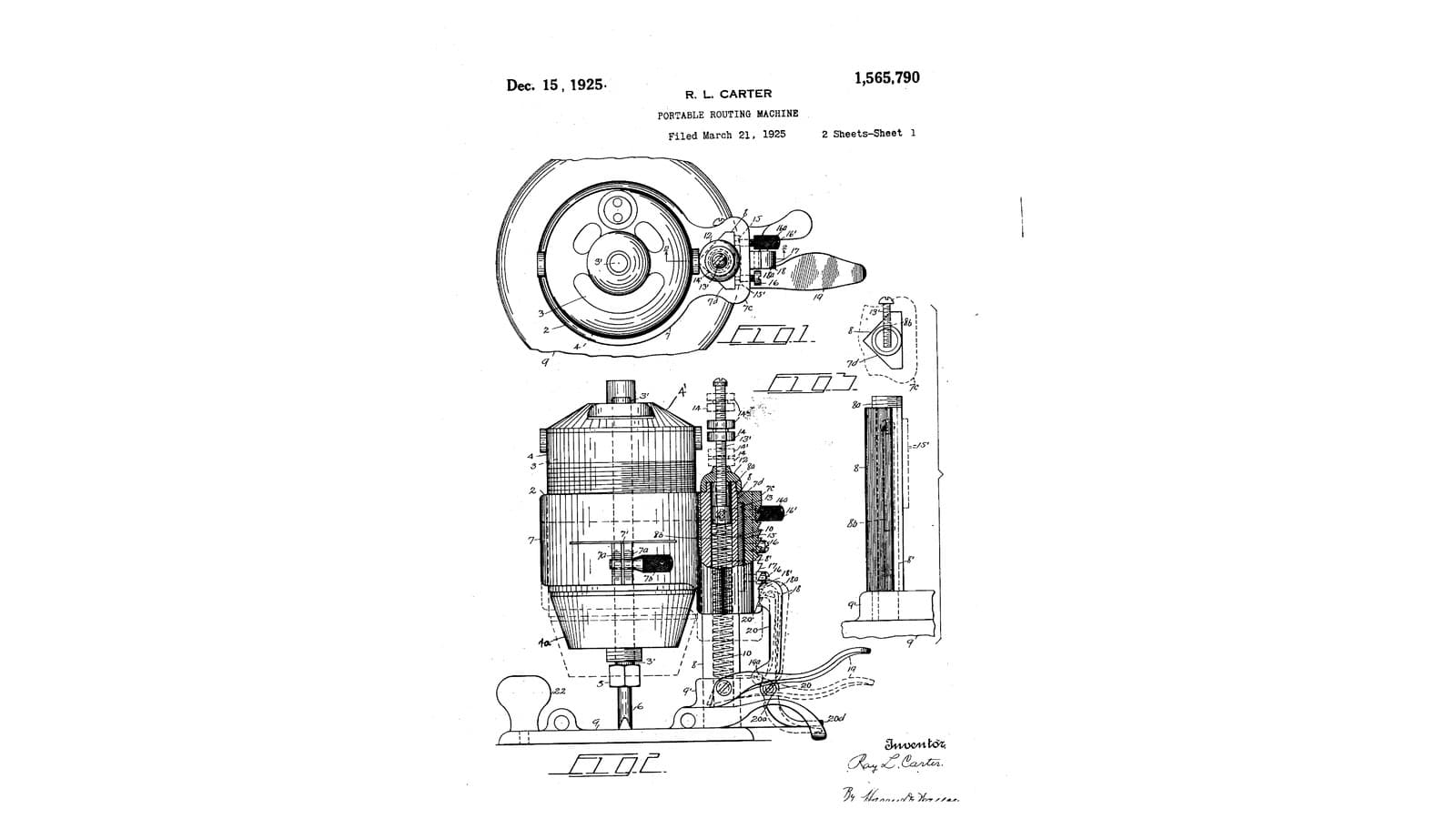
Rack-and-Pawl Plunge Router: The Motor Rides One Post on a Spring and Steps Down a Tooth at a Time (Carter, 1925)
por Forge
Marcenaria
12
0
0
0
0
0
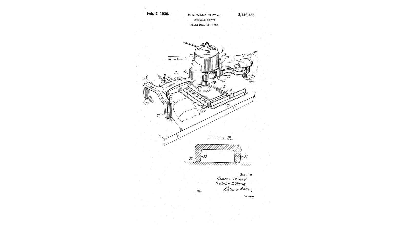
Three-Legged Router: A T-Frame on the Table Beside the Work, Its Depth Set by a Knob While Cutting (Willard & Young, 1939)
por Forge
Industry 3.0 — Assembly Line & Mass Production (1913)
6
0
0
0
0
0
CC0 Domínio Público
Este blueprint é liberado sob CC0. Você é livre para copiar, modificar, distribuir e usar este trabalho para qualquer finalidade, sem pedir permissão.
Apoie o Maker comprando produtos através do Blueprint, onde ele ganha uma Comissão Maker definida pelos vendedores, ou crie uma nova versão deste Blueprint e inclua-o como conexão no seu próprio Blueprint para compartilhar receita.