ARTE
BELEZA E BEM-ESTAR
ARTESANATO
CULTURA E HISTÓRIA
ENTRETENIMENTO
MEIO AMBIENTE
COMIDA E BEBIDAS
ENGENHARIA REVERSA
CIÊNCIAS
ESPORTES
TECNOLOGIA
TECNOLOGIA VESTÍVEL
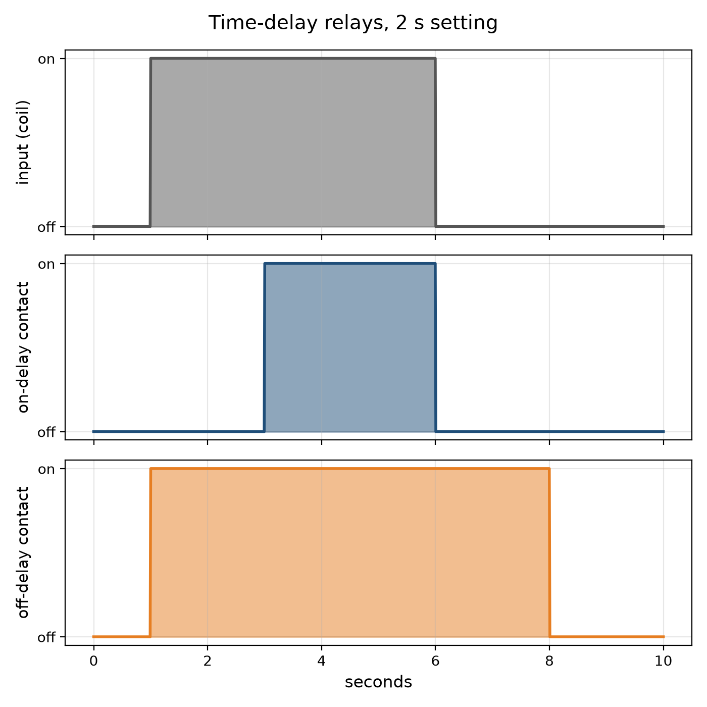
Youblob (generated from this blueprint's notebook) · CC0


The Time-Delay Relay: Switching a Set Time Later
Many control jobs need a pause: start the motor, wait until it is up to speed, then load it; stop the burner, then run the fan a little longer to clear the heat; light the stairway, and switch it off a few minutes later. The time-delay relay does it. An on-delay closes its contact a set time after it is energised; an off-delay keeps its contact closed a set time after it is de-energised.
The earliest timed their delay with a dashpot — a piston pushing air or oil through a small adjustable hole — or with a bimetal warmed by a heater. Electronic relays charge a capacitor through a resistor and switch when it reaches a threshold.
This rung works out an RC delay and why capacitor tolerance and leakage limit it, draws on- and off-delay timing, and builds an on-delay relay with a 555 timer.
Iniciante
About 3 hours
Instruções
1
1
The RC delay and its limits
The RC delay and its limits
A carregar o notebook Jupyter…
2
2
Build a 555 on-delay relay
Build a 555 on-delay relay
On a breadboard wire a 555 as a monostable from a 9–12 V supply: pins 4 and 8 to the supply, pin 1 to 0 V, a resistor R from the supply to pins 6 and 7 joined, a capacitor C from pins 6 and 7 to 0 V, 10 nF from pin 5 to 0 V, and pin 2 (trigger) held high through 10 kΩ with a push button to 0 V.
Pin 3 goes high for 1.1 RC after the button is pressed. Drive an NPN transistor from pin 3 through 1 kΩ, with the relay coil between the supply and the collector and a diode across the coil, reversed, to catch the coil's kick. Wire an LED through the relay's contact.
Time the relay with a stopwatch for three values of R. Plot delay against R: a straight line whose slope is 1.1 C. Swap in a second capacitor of the same marked value and watch the delay change — its tolerance.
Materiais para este passo:
 Circuito integrado temporizador NE5551 peça
 Transístor NPN1 peça
 Relé SPDT1 peça
 Díodo1 peça
 Kit de condensadores1 peça
 Kit de resistências1 peça
 Botão de pressão1 peça
 LED de 5 mm1 peça
 Placa de ensaio1 peça
 Fios de ligação1 peça
 Relé temporizador1 peça
Ferramentas necessárias:
 Fonte de alimentação de corrente contínua
 Multímetro
 Cronómetro
3
3
The relay it times
The relay it times
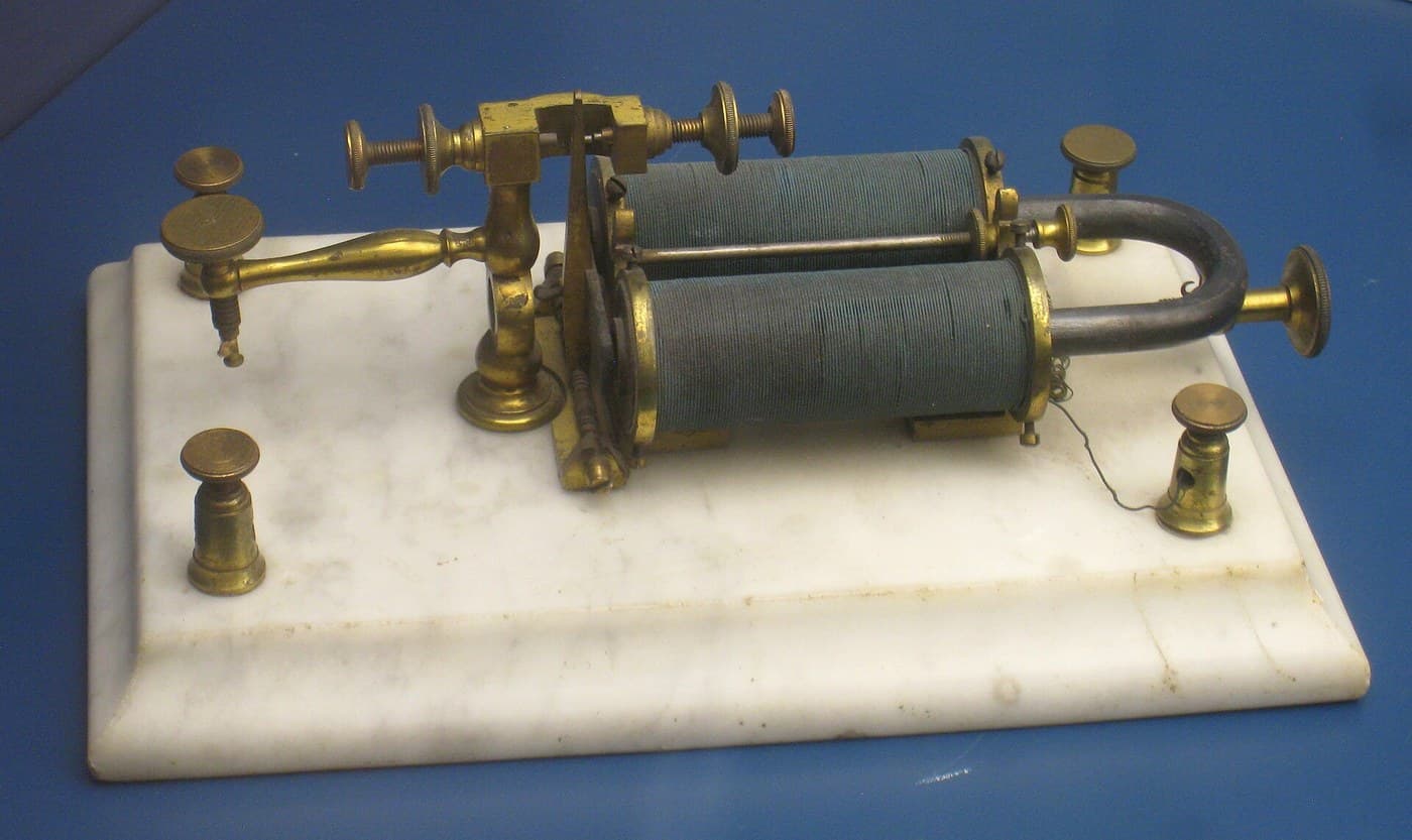
A time-delay relay is a relay with a clock in front of it. The embedded blueprint shows the electromagnetic relay it drives.
4
4
A timer that times wrong
A timer that times wrong
Time-delay relay faults.
Flow
Loading...
5
5
Context and honest limits
Context and honest limits
Pneumatic dashpot timers, thermal timers and motor-driven timers served machine and process control for decades; the 555 timer IC, introduced in 1972, made cheap electronic delays universal, and programmable controllers now provide timers in software.
**Honest limits.** An RC delay drifts with temperature and with the capacitor's age. For accurate long delays use a crystal-timed or counting timer. A relay switching mains loads must be wired and enclosed by someone qualified; the bench build stays at low voltage.
Materiais
11- Referência
- 1 peçaReferência
- 1 peçaReferência
- 1 peçaReferência
- 1 peçaReferência
- desdeR$29.22
- desdeR$2.62
- desdeR$18.32
- desdeR$48.85
- desdeR$8.29
- 1 peçaReferência
Ferramentas necessárias
3- Referência
- Referência
Blueprints relacionados
Estes blueprints compartilham conhecimento — técnicas, materiais ou princípios


CC0 Domínio Público
Este blueprint é liberado sob CC0. Você é livre para copiar, modificar, distribuir e usar este trabalho para qualquer finalidade, sem pedir permissão.
Apoie o Maker comprando produtos através do Blueprint, onde ele ganha uma Comissão Maker definida pelos vendedores, ou crie uma nova versão deste Blueprint e inclua-o como conexão no seu próprio Blueprint para compartilhar receita.