Test .stl Blueprint
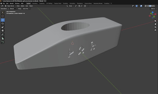
A 1 kg cross-peen hammer head with Elder Futhark runes ᚦᛟᚱ (Thurisaz-Othala-Raido, spelling TOR) engraved on both flat faces. The design follows the Hultafors Z 1000 profile: rounded square striking face, horizontal cross-peen for pushing metal, oval eye hole for the handle, and a center bulge around the eye for structural strength.
This blueprint covers the complete sand casting process — from 3D-printed pattern to finished hardened steel. The mold splits on the Y axis to capture the rune detail on both flat sides. A sand core creates the oval eye hole. After casting, quench hardening and tempering transform the soft cast steel into a working hammer head that holds up under forge work.
The 3D design file is provided in STL (Stereolithography) format — a universal 3D printing format compatible with all slicers and 3D viewers. Download it to print the pattern directly or import into any CAD software for modification.
Instrukcje
Download the 3D hammer head design
Download the 3D hammer head design
Download the Blender (.blend) design file containing the complete cross-peen hammer head geometry. The model is scaled to exactly 1 kg of hardened steel (7850 kg/m³ density, 127.4 cm³ volume). Final dimensions: 126 mm length × 43 mm width × 38 mm height. Elder Futhark runes ᚦᛟᚱ (TOR) are engraved 3 mm deep on both flat faces (+Y and -Y sides). The eye hole is an oval cylinder (18 mm radius, 65% Y compression) positioned slightly toward the striking face.
Open the file in any STL viewer or slicer (PrusaSlicer, Cura, MeshLab) to inspect and prepare for 3D printing. To modify the geometry, import into Blender or Fusion 360.
3D print the pattern at 102% scale
3D print the pattern at 102% scale
Export the hammer head from Blender as an STL file (File → Export → STL). In your slicer software, scale the model uniformly to 102% — this compensates for the approximately 2% linear shrinkage that occurs when cast steel cools from liquid to room temperature. Print in PLA or ABS at standard settings. The pattern does not need to withstand heat — it will be used at room temperature to create the sand impression.
After printing, sand any visible layer lines smooth. The sand will capture every surface detail, including print artifacts. Pay special attention to the rune engravings — use a small file or needle to clean any bridging or stringing inside the letterforms.
Split the pattern on the Y axis
Split the pattern on the Y axis
Cut the 3D-printed pattern in half along the Y axis (splitting through the center of both flat rune-engraved faces). This creates two halves, each carrying one set of rune engravings on its outer face. The Y-axis split is essential because the runes are the deepest surface detail — splitting here means each rune is a simple impression in the sand, not an undercut that would lock the pattern in the mold.
Glue alignment pins (two short dowel stubs) into one half so the halves register precisely when reassembled. The pins should protrude 5-8 mm and fit snugly into matching holes drilled in the other half.
Prepare green sand
Prepare green sand
Mix green sand: approximately 88% silica sand, 10% bentonite clay, and 2% water by weight. For this hammer head, prepare at least 40 kg of green sand to fill the cope and drag with adequate margin. Add the bentonite clay to dry silica sand and mix thoroughly by hand or with a muller until the clay is evenly distributed — no dry pockets, no clay lumps.
Add water gradually while mixing. Test the moisture by squeezing a handful: it should hold its shape when released and break cleanly when snapped in half. If it crumbles, add more water. If it feels sticky or won't release from your hand, it is too wet — add dry sand.
Materiały do tego kroku:
 Silica Sand40 kg
 Bentonite Clay5 kg
 Water2 litrów
Tools needed:
 Wooden Mixing Stick
Place one pattern half in the drag
Place one pattern half in the drag
Set the drag (bottom half of the flask) upside down on a flat board. Place one half of the split pattern flat-side down in the center of the drag, rune face pointing up. Position it so there is at least 50 mm of sand space on all sides between the pattern and the flask walls. The rune-engraved face is now the parting surface — this half of the rune detail will be captured in the cope later.
Tools needed:
 Cope and Drag Flask
Dust the pattern with parting powder
Dust the pattern with parting powder
Apply a thin, even coat of parting dust (talc, graphite powder, or lycopodium powder) over the entire pattern surface and the board around it. The parting dust prevents the green sand from sticking to the pattern and ensures clean separation when the pattern is removed. Tap the dust container gently — a fine dusting is sufficient. Heavy application leaves residue that fills fine rune details.
Materiały do tego kroku:
 Parting Dust0.1 kg
Ram green sand in the drag
Ram green sand in the drag
Sift a thin layer of fine-riddle sand (the same green sand passed through a fine sieve) directly over the pattern to capture surface detail. Then fill the drag with green sand in layers, ramming each layer firmly with a ramming tool or wooden dowel. Pack the sand tightly around the pattern, paying special attention to the eye hole area and the rune engravings — these concavities need sand pressed firmly into every corner.
Continue filling and ramming until the drag is full. Strike off the excess sand level with the top edge of the flask using a straight edge. The bottom of the drag is now complete.
Materiały do tego kroku:
Silica Sand20 kgTools needed:
 Sprue Pins
Flip the drag and seat the cope
Flip the drag and seat the cope
Flip the drag over so the pattern half faces up. The rune-engraved surface of the pattern is now exposed. Place the second pattern half onto the first, aligning it with the dowel pins. You now have the complete hammer head pattern sitting on the rammed drag sand, with the parting line at the Y-axis center.
Set the cope (top half of the flask) onto the drag, aligning the flask pins. Apply parting dust over the exposed pattern surface and all the drag sand visible around it — this prevents the cope sand from bonding to the drag sand.
Materiały do tego kroku:
Parting Dust0.1 kgTools needed:
Cope and Drag FlaskSet sprue and riser pins in the cope
Set sprue and riser pins in the cope
Position wooden sprue pins vertically in the cope. Place the main sprue pin (pouring channel) about 40 mm from one end of the pattern. Place a riser pin at the opposite end — the riser allows air and gas to escape and provides a reservoir of molten metal to feed the casting as it shrinks during solidification. Both pins should be smooth tapered dowels, approximately 15-20 mm diameter, standing taller than the cope depth.
Tools needed:
Sprue PinsRam green sand in the cope
Ram green sand in the cope
Sift fine-riddle sand over the second pattern half to capture the rune detail on this side. Then fill and ram the cope with green sand around the sprue and riser pins, building up in layers exactly as with the drag. Ram firmly but not so aggressively that the sand cracks — over-ramming makes the mold less gas-permeable and can cause porosity defects in the casting.
Strike off the top flush with the cope rim. Poke several thin vent holes through the cope sand with a wire (3-4 mm diameter) stopping just short of the pattern surface — these help gases escape during the pour.
Materiały do tego kroku:
Silica Sand20 kgRemove sprue pins and cut the gate
Remove sprue pins and cut the gate
Carefully withdraw the sprue and riser pins by twisting gently while pulling straight up. This leaves smooth cylindrical channels through the cope sand. At the base of the sprue channel (where it meets the parting surface), carve a shallow runner channel in the cope sand connecting the sprue to the mold cavity. This runner should be about 10 mm wide and 8 mm deep — it guides the molten metal from the vertical sprue into the horizontal mold cavity.
Cut a pouring basin (funnel shape) at the top of the sprue to make pouring easier and reduce turbulence.
Separate cope from drag and remove the pattern
Separate cope from drag and remove the pattern
Lift the cope straight up off the drag — the parting dust ensures clean separation. Set the cope aside on a flat surface, sand face up. Tap the pattern halves gently to loosen them from the sand (a light rap with a mallet on the pattern edge vibrates it free), then lift each half straight out. You should see a clean negative impression of the hammer head in both cope and drag sand, including the rune engravings.
Inspect the cavity for any crumbled sand, loose grains, or damaged rune detail. Repair minor damage by pressing the sand back with a smoothing tool. Blow out any loose particles.
Create a sand core for the eye hole
Create a sand core for the eye hole
The oval eye hole (where the handle fits) cannot be formed by the external pattern — it requires a sand core. Mix core sand: silica sand with a binder (linseed oil or sodium silicate, about 3% by weight). Pack this mixture into a cylindrical core box matching the eye hole dimensions from the 3D model: approximately 36 mm major axis, 23 mm minor axis (oval), and 60-70 mm long (long enough to span the full mold width and rest on core prints).
Bake the core at 200°C for 1-2 hours if using oil binder, or gas-harden with CO₂ if using sodium silicate. The core must be rigid enough to withstand the pressure of molten steel pouring around it.
Materiały do tego kroku:
Silica Sand1 kg Linseed Oil0.1 litr
Place the core and close the mold
Place the core and close the mold
Set the baked sand core into the eye hole impression in the drag. The core should sit in the core prints (recesses left by the pattern's eye cylinder, which extended beyond the mold cavity). The core prints support the core at both ends so it floats in the center of the cavity where the eye hole will be.
Lower the cope back onto the drag, aligning the flask pins precisely. Clamp or weight the cope down — molten steel exerts significant buoyant force on the cope sand. For a 1 kg casting, place at least 20 kg of weight on top of the cope or use C-clamps on the flask edges.
Tools needed:
Cope and Drag FlaskBuild the charcoal fire and preheat the crucible
Build the charcoal fire and preheat the crucible
Put on all safety equipment: leather apron, gauntlet gloves, face shield, safety boots. Build a deep charcoal bed in the forge and ignite it. Place the graphite-clay crucible in the forge and preheat it gradually over 20-30 minutes — a cold crucible plunged into high heat can crack from thermal shock. Use the bellows to raise the temperature steadily. The crucible must reach orange-white heat before adding steel.
Materiały do tego kroku:
 Charcoal5 kg
Tools needed:
 Graphite-Clay Crucible
 Bellows
 Leather Apron
 Leather Gauntlet Gloves
 Face Shield
 Safety Boots
Melt the steel
Melt the steel
Add 1.5 kg of medium-carbon steel (0.4-0.6% carbon) to the preheated crucible in small pieces — cut-up bar stock, clean scrap, or broken tool steel. Work the bellows continuously to maintain maximum temperature. Steel melts at approximately 1500°C (brilliant white heat). The extra 0.5 kg beyond the 1 kg hammer weight accounts for the sprue, riser, runner, and spillage.
Melting takes 30-60 minutes depending on forge capacity and bellows airflow. The steel is ready when the entire charge is liquid and glows white. Add a pinch of borax as flux to help slag float to the surface.
Materiały do tego kroku:
 Medium-Carbon Steel1.5 kgCharcoal5 kg
Tools needed:
Bellows Crucible Tongs
Skim slag and pour the molten steel
Skim slag and pour the molten steel
Using the crucible tongs, lift the crucible from the forge. Skim the floating slag layer off the surface with a steel rod or skimming ladle — slag inclusions weaken the casting and ruin the surface finish. Work quickly; the steel loses heat rapidly once removed from the forge.
Pour the molten steel in a single steady stream into the sprue basin. Do not hesitate or stop mid-pour — interrupted pouring creates cold shut defects where two metal fronts meet but do not fuse. Fill until molten steel rises in the riser hole, confirming the cavity is completely filled. The entire pour should take 5-10 seconds.
Tools needed:
Crucible Tongs Pouring Ladle
Allow the casting to cool
Allow the casting to cool
Do not disturb the mold. Allow the casting to cool in the sand for at least 2 hours — longer for heavy sections. The sand acts as an insulator, slowing the cooling rate and reducing internal stress. Premature breakout causes cracking from thermal shock, especially around the eye hole where thick and thin sections meet.
The sprue and riser metal will solidify last because they are the hottest sections. Steam and smoke from the mold are normal — the moisture in the green sand boils off as the steel heats the surrounding sand.
Break out the casting
Break out the casting
After cooling, remove the cope clamps/weights and lift the cope off. Break the sand away from the casting by hand — green sand crumbles easily. Lift the casting from the drag sand. The sand core inside the eye hole may need to be chipped and drilled out — baked core sand is harder than green sand.
Knock off clinging sand with a wire brush. The casting will have the hammer head shape with the sprue, riser, and runner still attached as solidified metal branches.
Tools needed:
 Wire Brush
 Forge Tongs
Cut the sprue and riser and clean the parting line
Cut the sprue and riser and clean the parting line
Cut the sprue, riser, and runner from the casting using a hacksaw or angle grinder. Cut as close to the casting surface as possible without gouging the hammer body. File the stubs flush with the surface. The parting line — a thin fin of metal where the cope and drag met — runs around the entire casting at the Y-axis center. File this flash off carefully, especially around the rune engravings where even a thin fin disrupts the letterforms.
Tools needed:
 Metal File
Inspect and dress the rune detail
Inspect and dress the rune detail
Examine the rune engravings on both flat faces under good light. Sand casting at this scale typically reproduces 1-2 mm detail well — the 3 mm deep rune strokes should be clearly legible. Use a small needle file or rotary tool to clean any rough edges, sand inclusions, or partially filled strokes. The rune strokes are 1 mm wide and should have crisp, squared-off edges after cleanup.
Check the eye hole for concentricity and smooth bore — ream with a round file if needed. The handle must fit tightly with a slight taper.
Tools needed:
Metal FileNormalize the casting
Normalize the casting
Cast steel has a coarse grain structure from slow cooling in the sand mold. Normalize it by heating the entire hammer head to cherry red (approximately 800°C) in the forge and letting it cool in still air. This refines the grain structure and relieves internal casting stresses. Repeat twice — each cycle produces a finer, more uniform grain.
Handle the hammer with forge tongs during heating. Heat evenly; do not let one section get significantly hotter than another, or you will introduce new stress.
Materiały do tego kroku:
Charcoal2 kgTools needed:
Forge TongsBellowsQuench harden the striking face
Quench harden the striking face
Fill the quench bucket with linseed oil or vegetable oil — never cold water for cast steel, as the thermal shock causes cracking. Heat the hammer head to cherry red (800°C) one final time. Plunge the striking face end into the oil quickly, submerging about two-thirds of the head. Hold it there for 10-15 seconds until the sizzling stops. The cross-peen end stays above the oil — it should remain slightly softer for toughness, as the peen absorbs impact forces differently than the striking face.
The rapid cooling transforms the crystal structure into martensite — extremely hard but brittle. The hammer will ring with a high pitch when tapped, and a file will skate across the surface without biting.
Materiały do tego kroku:
Linseed Oil3 litrówTools needed:
 Quench BucketForge Tongs
Temper the hammer head
Temper the hammer head
Polish the striking face with sandpaper to bright bare metal — you need to see the oxide temper colors. Place the hammer head in the forge at low heat or in a kitchen oven set to 280°C. Watch the polished surface: as the steel heats, oxide colors appear in sequence — pale straw at 220°C, bronze at 260°C, purple at 280°C, blue at 300°C.
For a working hammer head, target the purple-to-blue transition (280-300°C). This tempers the martensite just enough to restore toughness while retaining hardness — the striking face will dent soft steel without chipping. Hold at temperature for 30 minutes, then let it air cool. The hammer head is now ready for handle fitting and use.
Tools needed:
Forge TongsMateriały
7- 81 kgPlaceholder
- 5 kgPlaceholder
- 0.2 kgPlaceholder
- 3.1 litrówPlaceholder
- 1.5 kgPlaceholder
Wymagane narzędzia
15- Placeholder
- Placeholder
- Placeholder
- Placeholder
- Placeholder
- Placeholder
- Placeholder
- Placeholder
- Placeholder
- Placeholder
- Placeholder
- Placeholder
- Placeholder
- Placeholder
Materiały z połączonych planów

Casting a Tetsubin Iron Kettle — Sand Mold Method
autor: Forge![]()
Obróbka metali

Quench Hardening and Tempering a Steel Blade — Heat Treatment Fundamentals
autor: Forge![]()
Obróbka metali

Making a Clay Crucible for Smelting — The Vessel That Holds Molten Metal
autor: Forge![]()
Obróbka metali
Powiązane blueprinty
Te blueprinty dzielą się wiedzą — technikami, materiałami lub zasadami

Smelting Bog Iron in a Bloomery Furnace — From Ore to Wrought Iron
autor: Forge![]()
Obróbka metali

Building a Box Bellows — The Breath That Makes Metal Obey Fire
autor: Emma![]()
Obróbka drewna

Smelting Wootz Crucible Steel — The Indian Secret Behind Damascus Blades
autor: Forge![]()
RZEMIOSŁO

Smelting Copper from Malachite Ore — Extractive Metallurgy
autor: Forge![]()
Obróbka metali

Casting a Brass Candlestick — Medieval Foundry Work
autor: Forge![]()
Obróbka metali

Smelting Copper from Malachite — From Green Ore to Red Metal
autor: Peter![]()
Obróbka metali
CC0 Domena publiczna
Ten plan jest udostępniany na licencji CC0. Możesz go swobodnie kopiować, modyfikować, rozpowszechniać i wykorzystywać do dowolnych celów, bez konieczności uzyskiwania zgody.
Wesprzyj Makera kupując produkty przez jego plan, za co zarabia Prowizja Makera ustalony przez sprzedawców, lub stwórz nową iterację tego planu i dołącz go jako połączenie w swoim własnym planie, aby dzielić się przychodami.