ART
BEAUTY & WELLNESS
CRAFT
CULTURE & HISTORY
ENTERTAINMENT
ENVIRONMENT
FOOD & DRINKS
REVERSE ENGINEERING
SCIENCES
SPORTS
TECHNOLOGY
WEARABLES
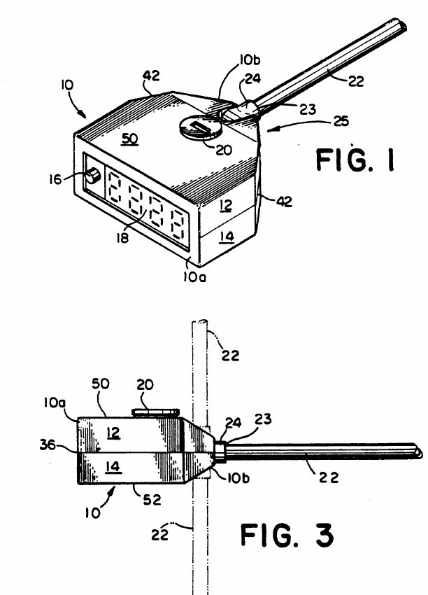


Instant-Read Thermometer: Digital, with a Stainless Probe That Pivots on the Case (Cook, US 5,018,875, 1991)
A pocket digital thermometer. A thin stainless steel probe with a thermistor in its tip pivots on a small, flat-sided case, so you can push the probe into food and turn the display to face you. A button cell runs a chip and a liquid crystal display, and a push button updates the reading at once. The angled case will not roll off a table.
Result: a thin-probe digital thermometer for food and air.
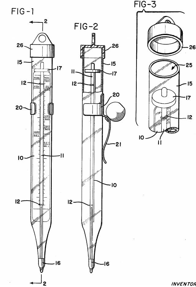
Source: T. A. Cook (PSG Industries), US 5,018,875 (1991). Unknown: the circuit, the range, the case size. Picture: the patent drawing.
Intermediate
Unknown
Instructions
1
1
Make the probe
Make the probe
Cut a type 304 stainless steel tube about 0.166 in (4.0 mm) across and 5 in (120 mm) long, and close one end. Set a thermistor inside the closed tip and run its two wires up the tube. Aluminium or titanium would also serve.
Materials for this step:
 Stainless Steel Tube1 probe
 NTC Thermistor Kit1 thermistor
 Copper Wire1 interconnecting wires
Tools needed:
 Hacksaw
 Soldering Iron
2
2
Mould the pivot boss and case
Mould the pivot boss and case
Mould from ABS a cylindrical pivot boss with a recess for the probe's open end and a channel right through it for the wires. Mould the case in an upper and a lower half that snap together, wider at the display end and tapering to the probe end so it cannot roll, with two projecting supports at the probe end, each with a pivot hole. Not given: the sizes.
Materials for this step:
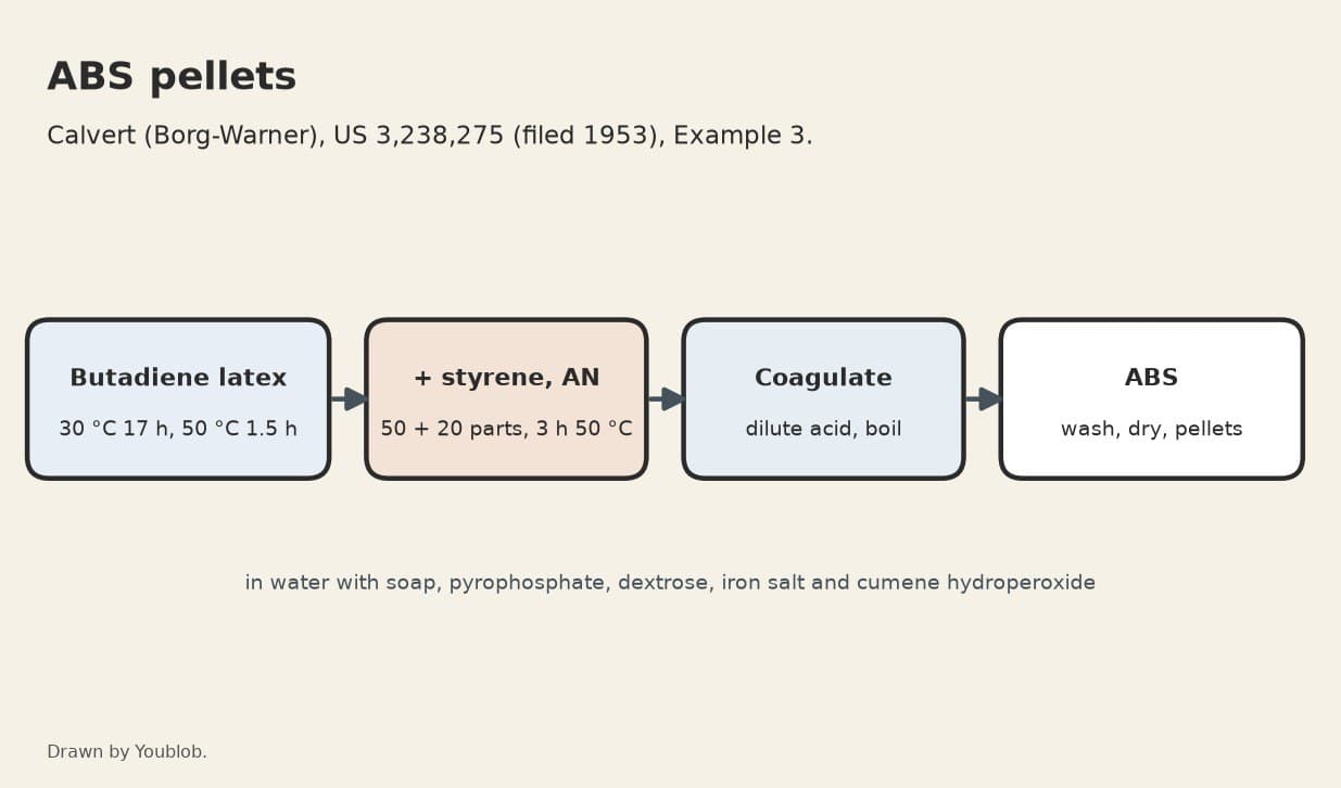
 ABS Pellets1 boss and case
Tools needed:
 Injection Moulding Machine
 Unknown Dimensions
3
3
Fit the electronics and assemble
Fit the electronics and assemble
In the case, fit an integrated circuit that turns the thermistor's resistance into a reading on a liquid crystal display at the wide end, with a push button beside it that updates the reading at once. Add a compartment for a 1.5 V button cell (Eveready E675, IEC R07) under a cover that locks with a quarter turn. Push the probe into the boss, lead the wires through the channel to the circuit, and clamp the boss ends in the pivot holes as the halves snap together; friction holds whatever angle you set. In use, push the probe in, turn the display to face you and press the button. Not given: the circuit (the patent points to US 4,536,851).
Materials for this step:
 Printed Circuit Board1 piece
 Integrated Circuit1 piece
 Segment LCD Panel1 piece
 Push Button1 piece
 1.5 V Button Cell1 piece
 Solder Wire1 as needed
Tools needed:
Soldering IronMaterials
10- 1 probePlaceholder
- 1 thermistorPlaceholder
- 1 interconnecting wiresPlaceholder
- 1 boss and casePlaceholder
- 1 piecePlaceholder
- 1 piecePlaceholder
- 1 piecePlaceholder
- Placeholder
- 1 piecePlaceholder
- 1 as neededPlaceholder
Tools Required
4- Placeholder
- 2 vendors sell this, none ship to you yetPlaceholder
- Placeholder
- Placeholder
Connected Blueprint Materials


This blueprint makes

Related Blueprints
These blueprints share knowledge with this one — techniques, materials, or principles that connect them in the learning graph.
CC0 Public Domain
This blueprint is released under CC0. You are free to copy, modify, distribute, and use this work for any purpose, without asking permission.
Support the Maker by purchasing products through their Blueprint where they earn a Maker Commission set by Vendors, or create a new iteration of this Blueprint and include it as a connection in your own Blueprint to share revenue.