
Collaboration
ART
BEAUTY & WELLNESS
CRAFT
CULTURE & HISTORY
ENTERTAINMENT
ENVIRONMENT
FOOD & DRINKS
REVERSE ENGINEERING
SCIENCES
SPORTS
TECHNOLOGY
WEARABLES
Washing Machine with Churn: One Crank Pounds the Wash, Turns the Tub and Works a Dash Churn (Wagoner & Severson, 1859)
YourGrandma

Created by

YourGrandma

11. November 2026IS
1
0
0
0
0

Washing Machine with Churn: One Crank Pounds the Wash, Turns the Tub and Works a Dash Churn (Wagoner & Severson, 1859)

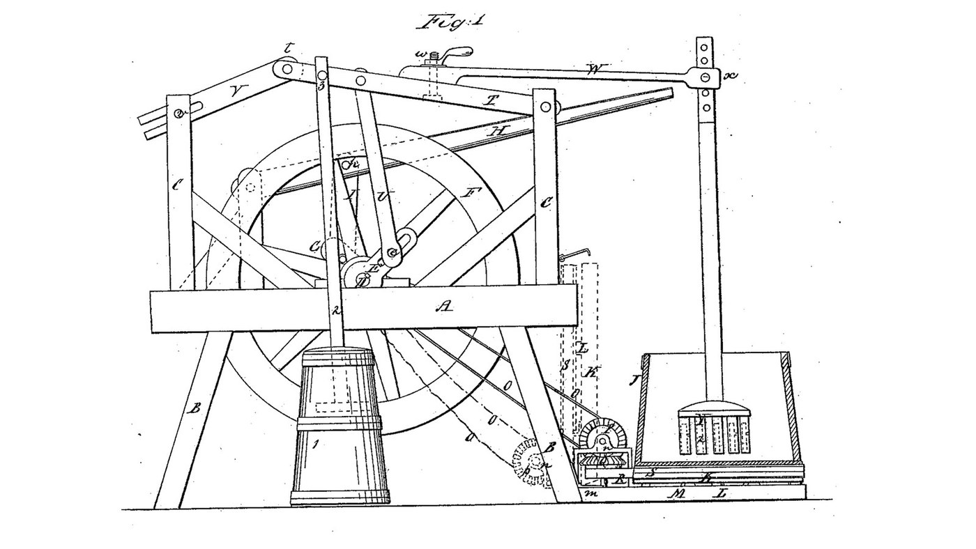
John Wagoner and Abram Severson Jr. of Guilderland Center, New York, received US 25,152, dated 16 August 1859, for a washing machine. A crank shaft with a heavy balance wheel rocks a long lever. A springy beam on the lever carries a pounder into the tub, and a belt and a pair of bevel wheels turn the tub slowly under it. The tub stands on a hinged platform: folded up it slackens the belt, and let down the tub's weight tightens it. A pin on the lever also works the dash of a churn standing beside the machine, with or without the washing. The patent gives no sizes; every size here is ours.
Advanced
About 5 days, plus printing

Instructions

1

Crank pin, strokes and tub speed

Loading Jupyter Notebook...
2

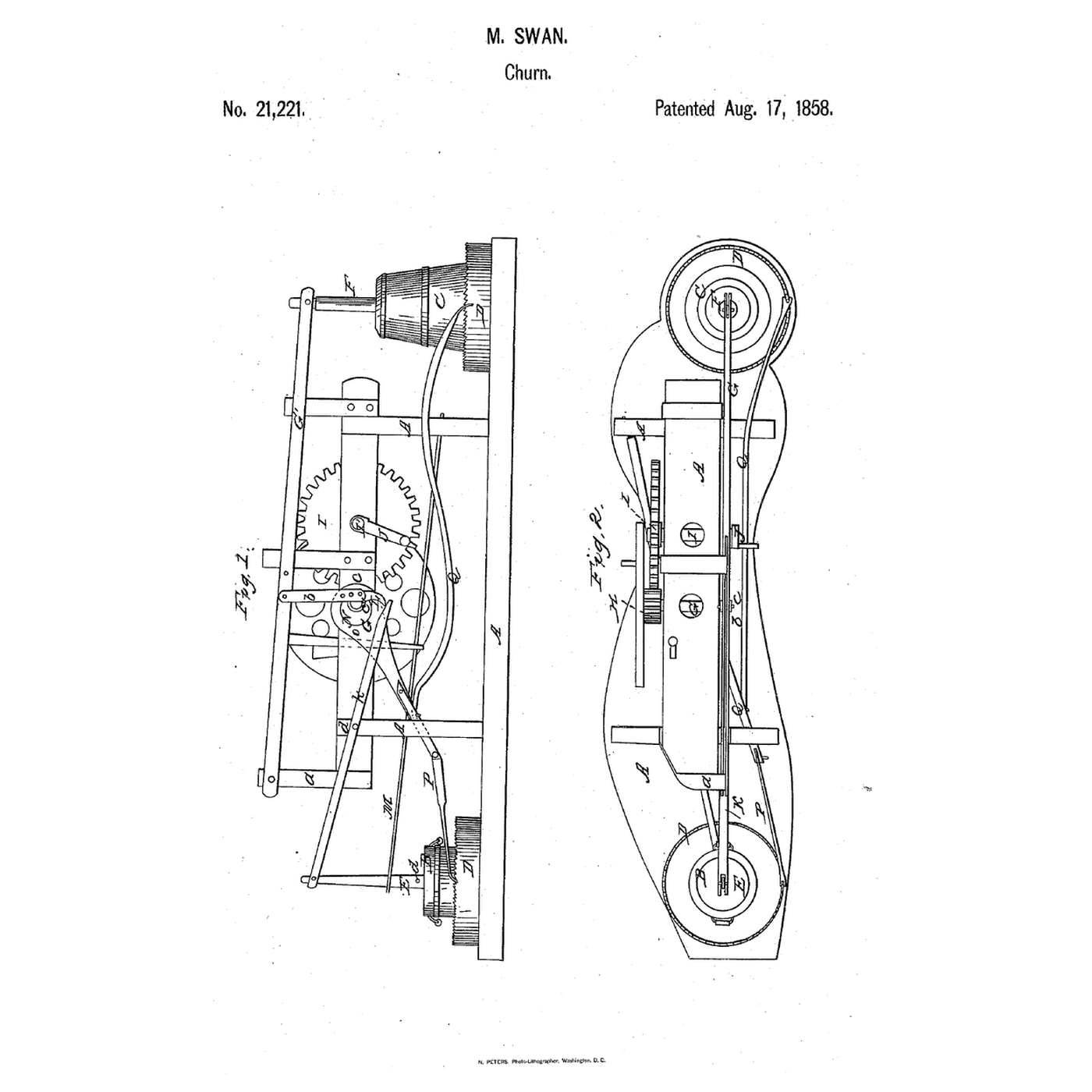
One crank working a churn and a washtub, a year before

Swan's machine lifted a plunger by a cam. Here a springy beam carries the pounder, and the tub's own weight tightens the belt that turns it.
3

Read US 25,152

"In addition to what has now been described our machine is adapted to operate a churn very effectively either alone or simultaneously with the washing operation." "We place the center of our tube J out of the plane of the motion of the levers T and V. Our pounder therefore inclines to strike on one side of J and not in the center thereby increasing the uniformity of the effect on the contents."
4

Print the pulley for shaft D

Flat-faced pulley 120 mm across and 40 mm wide, bored 31 mm for shaft D. PETG, 0.2 mm layers, 40 % infill, 4 walls.
Design FileSTLCC0 - Free
5

Print pulley R

Flat-faced pulley 100 mm across and 40 mm wide, bored 21 mm for the lower bevel wheel's shaft. PETG, 0.2 mm layers, 40 % infill, 4 walls.
Design FileSTLCC0 - Free
6

Frame A, legs B and uprights C

From 70 x 70 mm timber cut three stringers 1500 mm, two cross pieces 630 mm, four legs 700 mm, an upright 830 mm and an upright 720 mm. Bolt the cross pieces across the tops of the legs and the stringers on the cross pieces, 210 mm apart, so the frame's top is 840 mm from the floor. Bolt the long upright to the outside of the front stringer 100 mm from the left end and the short one 100 mm from the right end. Chisel an opening 50 x 260 mm through the left upright, from 440 to 700 mm above the stringer, and bore it across 560 mm up for pin v (a 16 mm bolt).

Materials for this step:

Softwood Timber 70x70mmSoftwood Timber 70x70mm11 m
Carriage BoltCarriage Bolt16 pieces
Flat WasherFlat Washer16 pieces
Nylon Insert Lock NutNylon Insert Lock Nut16 pieces

Tools needed:

Hand SawHand Saw
Cordless DrillCordless Drill
Drill Bit SetDrill Bit Set
Spade Bit SetSpade Bit Set
Mortise ChiselMortise Chisel
Wooden MalletWooden Mallet
Try SquareTry Square
Tape MeasureTape Measure
Adjustable SpannerAdjustable Spanner
Bar ClampBar Clamp
7

Shaft D, balance wheel F and crank E

Bolt three bearing blocks on the stringers' tops 650 mm from the left end and pass a 30 mm steel shaft D through them, 710 mm long. Build the balance wheel from three layers of 20 mm hardwood segments glued crossways: 840 mm across, a 100 mm rim and four spokes, 50 mm thick in all. Fit it on D between the front and middle stringers, the printed pulley between the middle and back stringers, and a hand crank 240 mm long on the back end. On the front end fit crank E, a hardwood arm 20 mm thick with a slot from 50 to 125 mm out, and a 20 mm bolt in the slot for the crank pin e.

Materials for this step:

Stainless Steel RodStainless Steel Rod1 piece
Bearing BlockBearing Block3 pieces
Hardwood BoardHardwood Board3 pieces
Wood GlueWood Glue1 piece
Hex Bolt AssortmentHex Bolt Assortment13 pieces
Nylon Insert Lock NutNylon Insert Lock Nut13 pieces
Shaft CollarShaft Collar2 pieces

Tools needed:

JigsawJigsaw
CompassCompass
Table SawTable Saw
Cordless DrillCordless Drill
Spade Bit SetSpade Bit Set
RouterRouter
Bar ClampBar Clamp
HacksawHacksaw
Adjustable SpannerAdjustable Spanner
8

Lever T, link U and rod V

Cut lever T from hardwood 40 x 70 mm, 1195 mm long. Bolt it to the front of the right upright, 610 mm above the stringer, free to rock. Join it to the crank pin by link U, hardwood 20 x 40 mm with its pin holes 560 mm apart, 715 mm from T's pivot. At T's left end join rod V, hardwood 30 x 40 mm, slotted 22 mm wide for 220 mm, and pass it through the left upright's opening astride pin v. Fix a steel pin 3, 24 mm and 370 mm long, through T 1015 mm from its pivot, sticking out at the front for the churn.

Materials for this step:

Hardwood BoardHardwood Board2 pieces
Hex Bolt AssortmentHex Bolt Assortment4 pieces
Flat WasherFlat Washer8 pieces
Nylon Insert Lock NutNylon Insert Lock Nut4 pieces
Stainless Steel RodStainless Steel Rod1 piece

Tools needed:

Table SawTable Saw
RouterRouter
Cordless DrillCordless Drill
Drill Bit SetDrill Bit Set
Spade Bit SetSpade Bit Set
HacksawHacksaw
SandpaperSandpaper
Adjustable SpannerAdjustable Spanner
Tape MeasureTape Measure
9

Spring beam W and the pounder

Cut the spring beam W from ash 30 x 40 mm, 1210 mm long. Lay it on T's top, its left end against a block glued on T, bolt it through T 415 mm left of the pivot with a wing nut (the hand nut w), and let it run past the upright to overhang the frame by 510 mm. Make rod X from hardwood 40 x 40 mm, 1090 mm long, with four holes at its top for height. Under it glue a hardwood head 200 x 120 mm with five legs 30 x 36 mm, 160 mm long, each slotted (Z) and bored across (z). Hang X from W's end on a bolt so it swings freely, in front of W.

Materials for this step:

Ash BoardAsh Board1 piece
Hardwood BoardHardwood Board1 piece
Wood GlueWood Glue1 piece
Hex Bolt AssortmentHex Bolt Assortment2 pieces
Wing NutWing Nut1 piece
Flat WasherFlat Washer4 pieces

Tools needed:

Table SawTable Saw
RouterRouter
Cordless DrillCordless Drill
Drill Bit SetDrill Bit Set
Mortise ChiselMortise Chisel
Wooden MalletWooden Mallet
SandpaperSandpaper
Bar ClampBar Clamp
10

Hinged platform M, bevel wheels and platform K

Make platform M from 40 mm hardwood, 860 x 860 mm, and hang it on two strap hinges (the butts m) at the feet of the right-hand legs. On M, 100 mm from the hinges, fit a 20 mm vertical shaft in a flange bearing with pulley R and the lower bevel wheel on it. In a hardwood post fit a 20 mm cross shaft with the upper bevel wheel and a 240 mm hardwood pulley P in line with the pulley on D. 480 mm from the hinges, 340 mm towards the front, set a 24 mm shaft L in a hardwood block that slides in a slot along M, with a compression spring pushing it away from R. Glue platform K, 660 mm across and 40 mm thick, bore it for L, and set four 40 mm hardwood wheels l under its edge.

Materials for this step:

Hardwood BoardHardwood Board4 pieces
Wood GlueWood Glue1 piece
Iron Strap HingeIron Strap Hinge2 pieces
Flange BearingFlange Bearing3 pieces
Bevel Gear Set (Steel, 1:1)Bevel Gear Set (Steel, 1:1)1 piece
Stainless Steel RodStainless Steel Rod1 piece
Shaft CollarShaft Collar3 pieces
Compression Spring AssortmentCompression Spring Assortment1 piece
Hardwood DowelsHardwood Dowels1 piece
Wood ScrewsWood Screws40 pieces
Hex Bolt AssortmentHex Bolt Assortment4 pieces
Nylon Insert Lock NutNylon Insert Lock Nut4 pieces
PETG FilamentPETG Filament1 piece

Tools needed:

FDM 3D PrinterFDM 3D Printer
JigsawJigsaw
CompassCompass
RouterRouter
Cordless DrillCordless Drill
Drill Bit SetDrill Bit Set
Spade Bit SetSpade Bit Set
HacksawHacksaw
Bar ClampBar Clamp
Adjustable SpannerAdjustable Spanner
11

Belts O and S, and the fold

Put belt S round pulley R and platform K's rim. Fold M up against the frame, run a string round the pulley on D and pulley P, and choose belt O just short enough that, with M let down and empty, it holds M at a slight angle; "The belt O is sufficiently short to hold the platform M at a slight angle until the weight of J is added thereto." Set the wooden tub J on K: its weight should pull M flat and the belt tight. Oil the wood.

Materials for this step:

Drive BeltDrive Belt2 pieces
Wooden TubWooden Tub1 piece
Boiled Linseed OilBoiled Linseed Oil1 piece

Tools needed:

Tape MeasureTape Measure
12

The build in 3D

FreeCAD model of this build: the frame, shaft D with the balance wheel and crank E, lever T with link U and rod V, the spring beam W and the pounder in the tub (front of the tub cut away), the hinged platform M with the bevel wheels, pulleys and belts, and the churn on pin 3. The crank was turned through 18 positions.
Design FileBLENDCC0 - Free
13

Wash

Put warm water, soap and the clothes in the tub, and set the pounder's height so its feet clear the tub's bottom by the clothes. Turn the hand crank steadily. The pounder rises and falls on one side of the tub while the tub turns under it, so every part of the wash comes under it in turn. Move the crank pin out in its slot for a longer stroke, in for a shorter one. Lift the clothes out to rinse and wring.

Tools needed:

WaterWater
Bar SoapBar Soap
14

Churn on pin 3

Make the dash 2: a hardwood rod 35 mm across, 1250 mm long, bored at the top to hang on pin 3, with two crossed blades 220 x 30 x 20 mm at the bottom. Stand the churn under pin 3, beside the machine, pour in about 10 litres of cream at about 15 °C (checked with the thermometer), a third of its height, pass the dash through the lid and hang it on pin 3. Turn the crank, with or without the wash, timing it. When the butter comes, lift the dash off the pin, drain the buttermilk, wash the butter in cold water, salt and weigh it.

Materials for this step:

Heavy CreamHeavy Cream10 l
Coarse Sea SaltCoarse Sea Salt1 piece
Hardwood BoardHardwood Board1 piece
Hardwood DowelsHardwood Dowels1 piece

Tools needed:

Butter ChurnButter Churn
Leave-In Probe ThermometerLeave-In Probe Thermometer
StopwatchStopwatch
Digital Kitchen ScaleDigital Kitchen Scale
Stainless Steel Mixing Bowl (Large)Stainless Steel Mixing Bowl (Large)
WaterWater
Cordless DrillCordless Drill
Spade Bit SetSpade Bit Set
Hand SawHand Saw
15

Troubleshooting

Washing machine troubleshooting.

Flow

Loading...
16

History and honest limits

**John Wagoner and Abram Severson, Jr.** of Guilderland Center, New York, US 25,152, 16 August 1859, "Washing-Machine". They claimed mounting the platform K and the pulleys and gearing P Q R on the hinged platform M, so turning M up slackens belt O and turning it down lets the tub's weight tighten it. The patent gives no sizes; every size here is ours. Their hand lever H and rod I, a second way to turn D, are not built: we turn D by a crank, which the patent allows. The spring that urges K's centre against belt S is "not represented" in their drawing; ours is a compression spring in a slot.

Materials

24

Tools Required

24

Design Files

3

CC0 Public Domain

This blueprint is released under CC0. You are free to copy, modify, distribute, and use this work for any purpose, without asking permission.

Support the Maker by purchasing products through their Blueprint where they earn a Maker Commission set by Vendors, or create a new iteration of this Blueprint and include it as a connection in your own Blueprint to share revenue.

Discussion

(0)

Log in to join the discussion

Loading comments...