Colaboração
ARTE
BELEZA E BEM-ESTAR
ARTESANATO
CULTURA E HISTÓRIA
ENTRETENIMENTO
MEIO AMBIENTE
COMIDA E BEBIDAS
ENGENHARIA REVERSA
CIÊNCIAS
ESPORTES
TECNOLOGIA
TECNOLOGIA VESTÍVEL
Turning-Tub Churn: A Crank Spins the Tub on a Geared Pedestal Against Two Fixed Triangular Beaters Held From Standards
Buttercup

Criado por

Buttercup

11. novembro 2026IE
7
0
0
0
0

Turning-Tub Churn: A Crank Spins the Tub on a Geared Pedestal Against Two Fixed Triangular Beaters Held From Standards

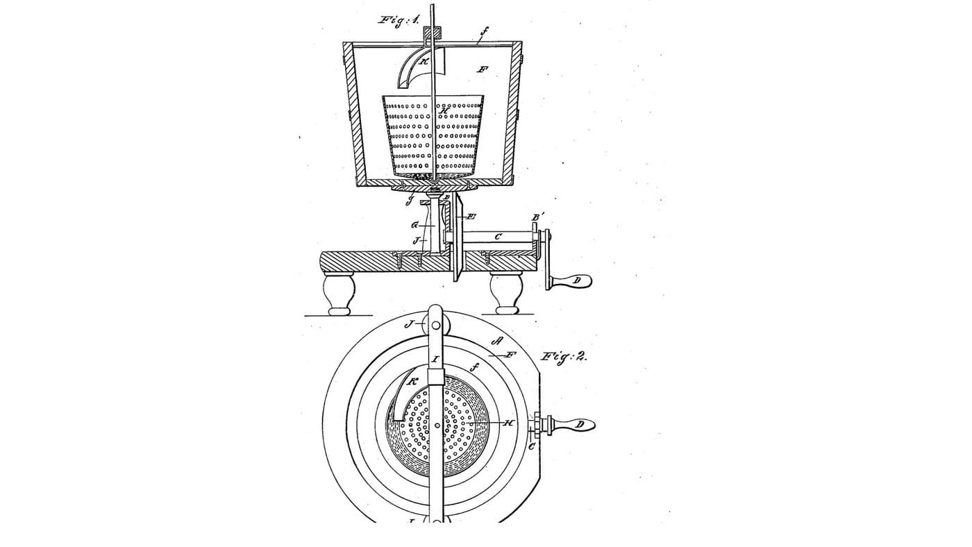
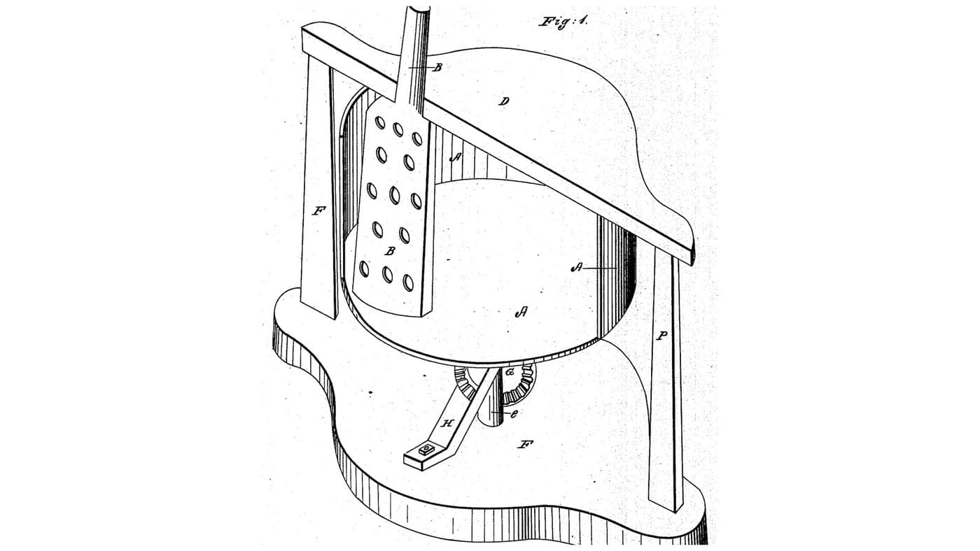
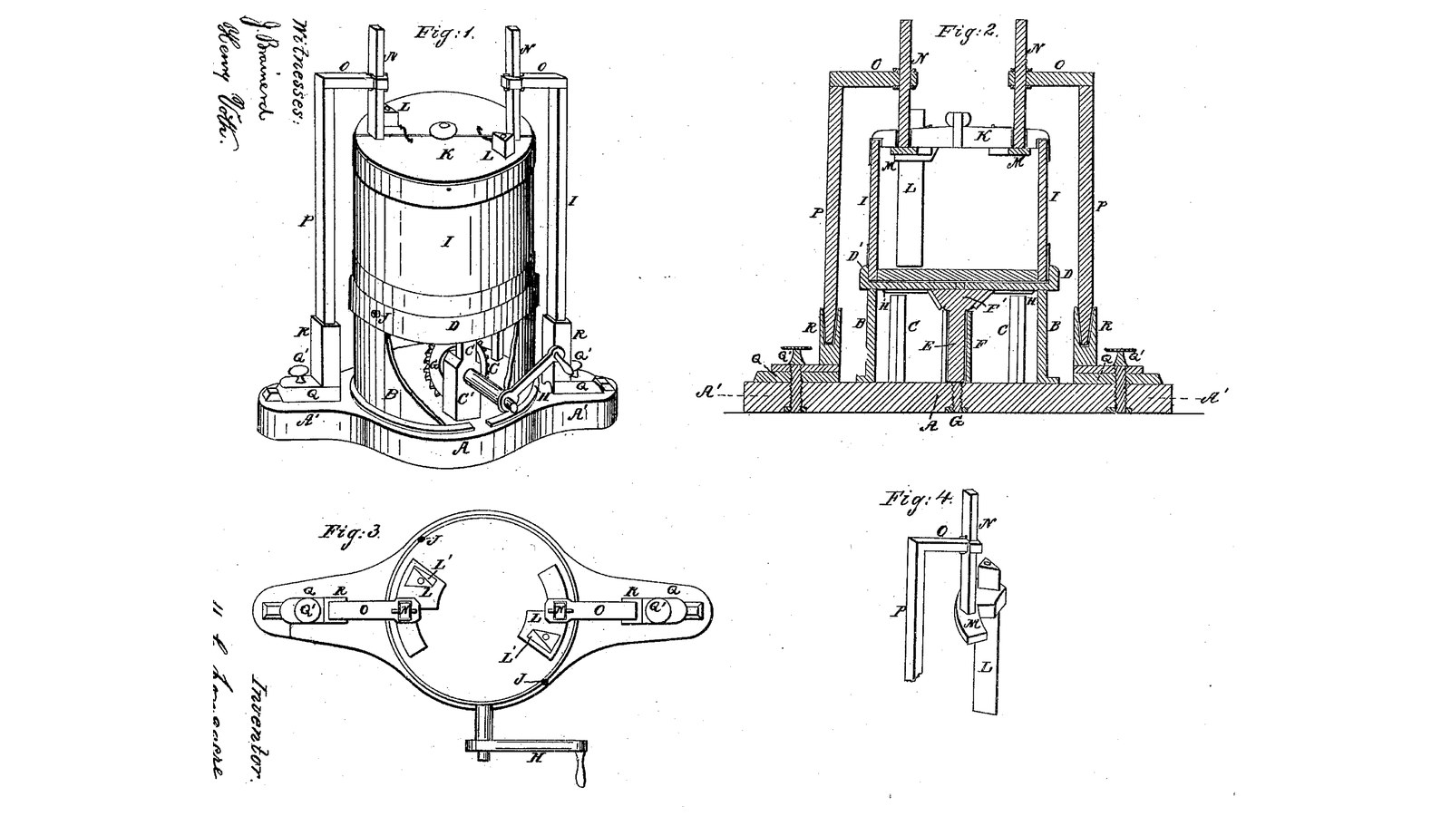
M. C. Longacre of Cleveland, Ohio, received US 31,355, dated 5 February 1861, for a churn that turns the tub instead of the dasher. A crank and bevel gears hidden in a drum on the base spin a disk on which the tub, or a common pail, stands. Two triangular wooden beaters, each with a hole along it for air, hang still inside the tub from arms on two standards and can be set nearer the wall or deeper. The tub throws the cream outward and the beaters throw it back. The patent gives no sizes; every size here is ours.
Avançado
About 3 days

Instruções

1

How fast to turn the tub

A carregar o notebook Jupyter…
2

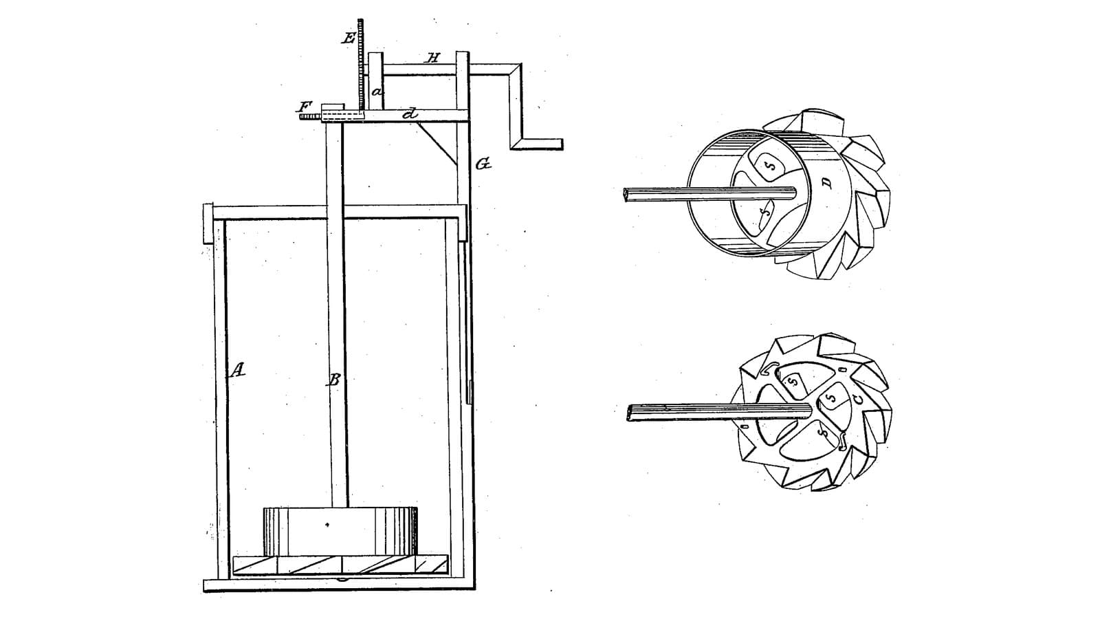
A turning vessel against a fixed break, a year and a half before

Harsha also turns the vessel against something fixed. Longacre stands the tub upright on a geared pedestal and makes the fixed beaters adjustable.
3

Read US 31,355

"Now, if the crank H is turned, the tub I, and disk D will receive a rotary motion, and the centrifugal force, tending to throw the fluid to the walls of the tub, the beaters at the same time tending to throw the same fluid back toward the center, the cream or milk has thus two forces constantly acting upon it, one a centrifugal, and the other a centripetal."
4

Base A, cylinder B and posts C

Glue up a hardwood base A 40 mm thick, a 400 mm circle with ends 120 mm wide running out to 700 mm overall. Cut a 30 mm slot 120 mm long along each end for the standards' feet. Roll a strip of 1.5 mm stainless sheet 168 mm wide into a cylinder B 310 mm across, rivet the lap, and screw it to the base through small tabs. Screw three hardwood posts C 40 mm square and 170 tall inside it, 110 mm from the centre and a third of a turn apart, the first at the back. Bore the cylinder 16.6 mm at the front, 97 mm up, for the crank shaft.

Materiais para este passo:

Tábua de madeira de leiTábua de madeira de lei3 peças
Cola de madeiraCola de madeira1 peça
Chapa de aço inoxidávelChapa de aço inoxidável1 peça
Rebites cegosRebites cegos6 peças
Parafusos para madeiraParafusos para madeira16 peças

Ferramentas necessárias:
Serra de mesaSerra de mesa
BússolaBússola
Serra tico-ticoSerra tico-tico
TupiaTupia
Tesoura de chapaTesoura de chapa
Kit de rebitadoraKit de rebitadora
Berbequim sem fiosBerbequim sem fios
Jogo de brocasJogo de brocas
Sargento de barraSargento de barra
Conjunto de chaves de fendasConjunto de chaves de fendas
5

Print the cog wheel E'

The cog wheel E' on the spindle under the disk: 14 teeth, module 2.5, 16.2 mm bore, its hub up. PETG, 0.2 mm layers, 30 % infill, 4 walls.
Arquivo de designSTLCC0 - Free
6

Print the driving wheel G

The driving wheel G on the crank shaft: a crown wheel of 42 teeth, module 2.5, 16.2 mm bore. PETG, 0.2 mm layers, 30 % infill, 4 walls.
Arquivo de designSTLCC0 - Free
7

Step G, pipe box F, spindle E, gears and crank H

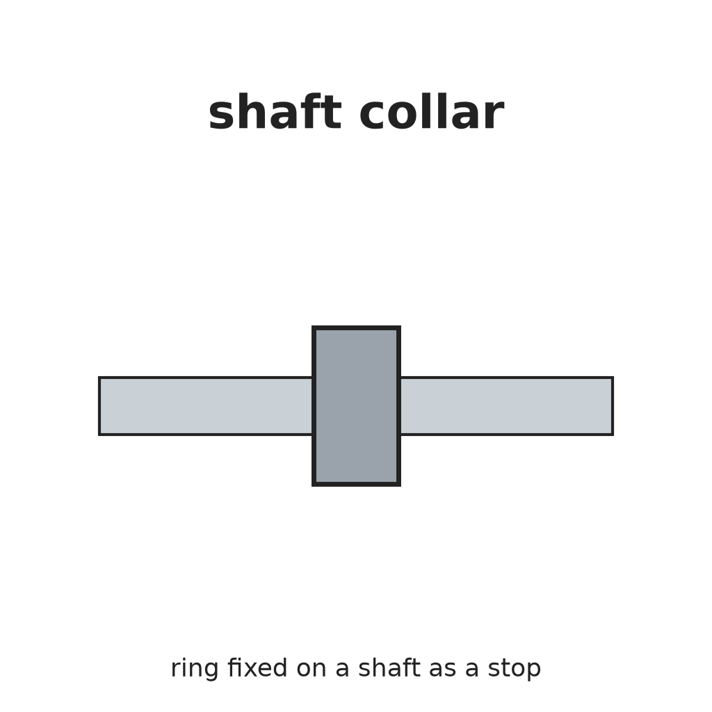
Bore the base's centre 8.4 mm and run an M8 bolt up through it with a nut each side, its head the step G, so it can be screwed up or down. Set a stainless tube F 30 mm long round it. Cut a 16 mm stainless spindle E 185 mm long; pin the cog wheel E' on it with its teeth 150 mm above the base. Screw a hardwood bearing block C' 40 x 25 x 120 mm to the base 55 to 80 mm in front of the centre, bored 16.6 mm across 97 mm up. Run a 16 mm stainless crank shaft 250 mm long through the cylinder and block, with the wheel G pinned on its inner end meshing E' from below and its end stopping clear of the spindle, a shaft collar against the block, and a crank H of mild steel flat bar, 100 mm throw, with a hardwood handle.

Materiais para este passo:

Sortido de parafusos sextavadosSortido de parafusos sextavados1 peça
Porca sextavadaPorca sextavada2 peças
Tubo de aço inoxidávelTubo de aço inoxidável1 peça
Varão de aço inoxidávelVarão de aço inoxidável2 peças
Tábua de madeira de leiTábua de madeira de lei1 peça
Shaft CollarShaft Collar1 peça
ContrapinoContrapino3 peças
Barra chata de aço macioBarra chata de aço macio1 peça
Cavilhas de madeira duraCavilhas de madeira dura1 peça
Filamento PETGFilamento PETG1 peça

Ferramentas necessárias:
Impressora 3D de filamento (FDM)Impressora 3D de filamento (FDM)
Berbequim sem fiosBerbequim sem fios
Jogo de brocasJogo de brocas
Serra de arco para metaisSerra de arco para metais
Limas (lima de mão)Limas (lima de mão)
Torno de bancadaTorno de bancada
Chave inglesa ajustávelChave inglesa ajustável
Conjunto de chaves de fendasConjunto de chaves de fendas
8

Disk D, flange D', bead H and tub I

Cut an 18 mm HDPE disk D 330 mm across, bore it 16.2 mm at the centre and fix it on the spindle's top. Screw under it a bead H, an HDPE ring 230 mm across outside and 210 inside, 2 mm thick, and on top a flange ring D' 300 mm across outside and 282 inside, 15 high, that the bucket's foot just drops into. Screw the step G up until the bead just touches the posts' tops. Use a 20-litre food-grade bucket as the tub I; for the patent's set screws J, two machine screws through the flange bearing on the bucket's foot.

Materiais para este passo:

Chapa de PEADChapa de PEAD2 peças
Parafusos para madeiraParafusos para madeira12 peças
Balde de 20 litrosBalde de 20 litros1 peça
Sortido de parafusos sextavadosSortido de parafusos sextavados2 peças

Ferramentas necessárias:

BússolaBússola
Serra tico-ticoSerra tico-tico
Conjunto de brocas de páConjunto de brocas de pá
Berbequim sem fiosBerbequim sem fios
Jogo de brocasJogo de brocas
Chave inglesa ajustávelChave inglesa ajustável
Conjunto de chaves de fendasConjunto de chaves de fendas
9

Beaters L, supports M, stems N, arms O, standards P and cover K

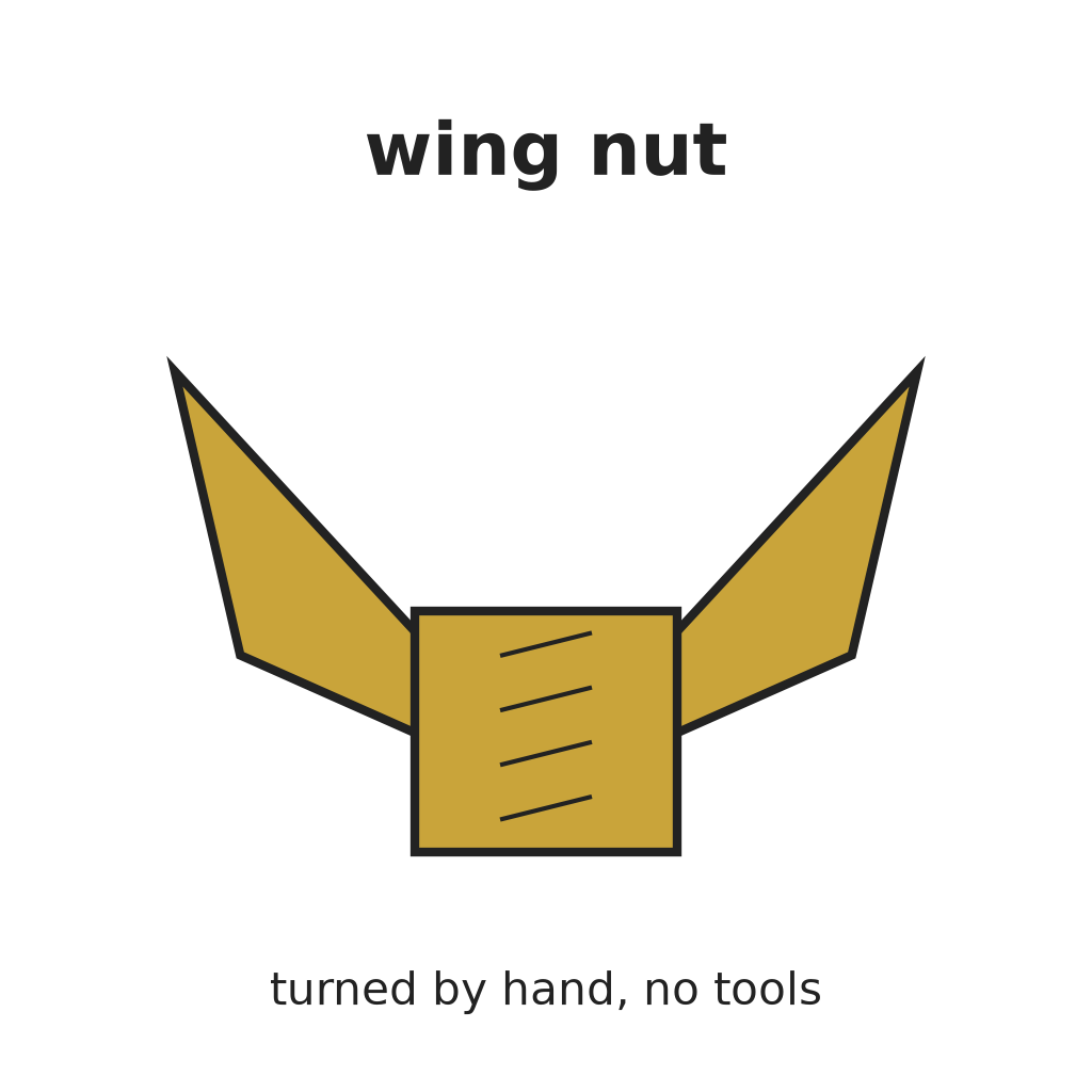
Plane two hardwood beaters L to a triangle 40 mm a side, 330 long, and bore a 10 mm hole through each lengthwise for air. Cut two hardwood supports M 50 x 40 x 65 mm with a triangular socket below for a beater's top and a 20 mm square socket above for a stem; glue the beaters in. Cut two hardwood stems N 20 mm square, 170 long, and fit each in its support. Make two standards P 40 x 40 mm, 650 tall, each on a foot Q 60 x 80 x 20 mm with a carriage bolt down through the base's slot and a wing nut Q' under it, so the standards slide in and out; let each stand in a socket in its foot (R) so it lifts out. Fix a hardwood arm O 30 mm square across the top of each standard, reaching in to its stem, with a 20 mm square hole and a wing-nut clamp bolt so the stem can be set higher or lower. Cut an HDPE cover K 304 mm across in two halves, notched for the stems.

Materiais para este passo:

Tábua de madeira de leiTábua de madeira de lei2 peças
Cola de madeiraCola de madeira1 peça
Parafuso de carroçariaParafuso de carroçaria4 peças
Porca borboletaPorca borboleta4 peças
Anilha planaAnilha plana4 peças
Chapa de PEADChapa de PEAD1 peça

Ferramentas necessárias:

Serra de mesaSerra de mesa
Conjunto de formões para madeiraConjunto de formões para madeira
Berbequim sem fiosBerbequim sem fios
Jogo de brocasJogo de brocas
Conjunto de brocas de páConjunto de brocas de pá
Serra tico-ticoSerra tico-tico
Chave inglesa ajustávelChave inglesa ajustável
Fita métricaFita métrica
10

The build in 3D

FreeCAD model of this build, the drum, disk and tub cut open: the base with its slotted ends, the drum, posts and bearing block, the step, spindle, cog wheel and driving wheel with the crank, the disk with its bead and flange, the bucket, and the two beaters hanging from their supports, stems, arms and standards.
Arquivo de designBLENDCC0 - Free
11

Churn

Set the bucket in the flange and pour in about 8 litres of heavy cream at about 15 °C, checked with the thermometer. Set the beaters close to the wall and reaching near the bottom without touching, and lay on the cover halves. Turn the crank steadily, timing it, not so fast that the cream climbs to the rim. When the butter comes, keep turning a little so it gathers in a mass. Lift off the cover and beaters, lift the bucket off the disk, take out the butter, pour the buttermilk into a bowl, wash the butter in cold water until it runs clear, salt and weigh it.

Materiais para este passo:

Natas para baterNatas para bater8 l
Sal marinho grossoSal marinho grosso1 peça
ÁguaÁgua1 peça

Ferramentas necessárias:

Termómetro de sonda permanenteTermómetro de sonda permanente
CronómetroCronómetro
Balança digital de cozinhaBalança digital de cozinha
Taça grande de aço inoxidávelTaça grande de aço inoxidável
12

Troubleshooting

Turning-tub churn troubleshooting.

Flow

Loading...
13

History and honest limits

**M. C. Longacre** of Cleveland, Cuyahoga County, Ohio, assignor to himself and R. R. Herrick, US 31,355, 5 February 1861, "Churn". He claimed "rotating the body of the churn in a vertical position by means of the disk (C) or its equivalent, when connected with the stationary dashers (L) arranged as described, for the purpose of adjusting the same both vertically and horizontally". His text uses the letters G and H each for two parts (the step and the driving wheel; the bead and the crank). His gears were bevel wheels; ours are a printed pinion and crown wheel, and our drum is stainless sheet. The patent gives no sizes; every size here is ours.

Materiais

22

Ferramentas necessárias

22

Ficheiros de design

3

CC0 Domínio Público

Este blueprint é liberado sob CC0. Você é livre para copiar, modificar, distribuir e usar este trabalho para qualquer finalidade, sem pedir permissão.

Apoie o Maker comprando produtos através do Blueprint, onde ele ganha uma Comissão Maker definida pelos vendedores, ou crie uma nova versão deste Blueprint e inclua-o como conexão no seu próprio Blueprint para compartilhar receita.

Discussão

(0)

Entrar para participar da discussão

Carregando comentários...